Range Rover Evoque: Diesel misfuelling protection device
 When the misfuelling device is
activated, it may cause fuel to be
discharged from the filler neck.
When the misfuelling device is
activated, it may cause fuel to be
discharged from the filler neck.
Note: It is the driver’s responsibility to fill the vehicle with the correct fuel. The diesel misfuelling protection device only reduces the risk of filling the vehicle with the incorrect fuel.
Diesel engine vehicles in some markets are equipped with a misfuelling protection device, incorporated into the fuel filler neck.
If the narrow filler nozzle fitted to pumps delivering unleaded petrol is fully inserted into the filler neck, the misfuel protection device will activate.
Note: The filler spout on some fuel cans and older fuel pumps may trigger the misfuelling device.
When activated, the yellow misfuel protector will be visible inside the filler neck. It will prevent fuel flow into the tank. Before fuelling can continue with the correct fuel, the device will need to be reset.
The reset tool is located in the luggage compartment.
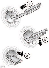
Reset the misfuel protection device as follows: 1. Insert the reset tool with the teeth uppermost, as far as it will go into the filler neck.
2. Locate the teeth by pushing down the top of the reset tool.
3. WIth the top of the tool pressed down and the teeth engaged, slowly pull the tool out of the filler neck to reset the device.
 Do not twist the device,
once the teeth
have engaged.
Do not twist the device,
once the teeth
have engaged.
Note: The yellow part of the protection device should no longer be visible in the filler neck.
Return the reset tool to the luggage compartment.
READ NEXT:
 Fuel tank capacity
Avoid the risk of running out of fuel and never
intentionally drive the vehicle when the fuel
gauge indicates that the tank is empty. When
refuelling your vehicle after the fuel gauge
reads empty,
Fuel specification
Diesel vehicles in Algeria,
Egypt, Libya,
Morocco, India, Pakistan and Tunisia
must only use premium diesel fuel.
Fuel consumption
The fuel consumption figures shown below have been calculated using a
standard testing
procedure (the new EC test procedure from Directive 99/100/EC), and produced in
accordance with
The Passeng
SEE MORE:
Important information
The information contained in this handbook covers all vehicle derivatives and
optional equipment,
some of which may not be fitted to your vehicle. Due to printing cycles, this
handbook may include
descriptions of options before they become generally available.
The vehicle options, hardware an
Symbols used in this handbook
Safety warnings indicate either a procedure which must be followed
precisely, or
information that should be considered with great care, in order to avoid the
possibility
of personal injury.
Cautions indicate either a procedure which must be followed precisely, or
information that
should
