Range Rover Evoque: Front Lower Arm
Removal
NOTES:
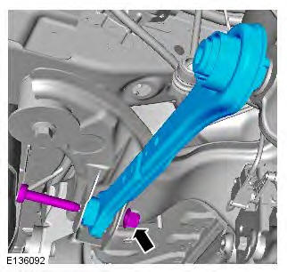
Some variation in the illustrations may occur, but the essential information is always correct.
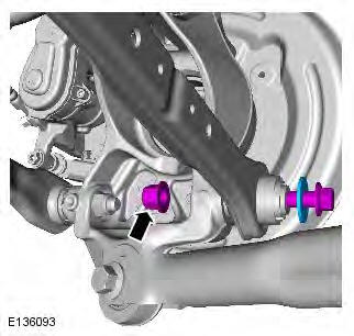
Front wheel drive transmission illustrations shown, all wheel wheel drive transmission is similar.
1. WARNING: Make sure to support the vehicle with axle stands. Raise and support the vehicle.
2. Refer to: Wheel and Tire (204-04 Wheels and Tires, Removal and Installation).
3.

4.
Installation
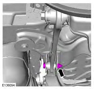
1. CAUTION: Only tighten the nut and bolt finger tight at this stage.

2. CAUTION: Only tighten the nut and bolt finger tight at this stage.
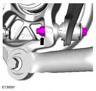
3. CAUTION: Nuts and bolts must be tightened with the weight of the vehicle on the suspension.
Support weight of vehicle on a jack at the rear hub.
4. Torque: 175 Nm
5. Torque: 175 Nm
6. Refer to: Wheel and Tire (204-04 Wheels and Tires, Removal and Installation).
READ NEXT:
 Rear Lower Arm AWD
Special Tool(s)
205-857
Remover, Halfshaft
Removal
CAUTION: LH illustration shown, RH is similar.
NOTE: Some variation in the illustrations may occur, but the essential
information is always correct.
Rear Stabilizer Bar
Removal
NOTES:
Some variation in the illustrations may occur, but the essential
information is always correct.
Removal steps in this procedure may contain installation details.
1. WARNING: Make sure
Wheel Knuckle
Special Tool(s)
205-857
Remover, Halfshaft
JLR-204-804
Lever, Wheel Knuckle
Removal
CAUTIONS:
Nuts and bolts must be tightened with the weight of the vehicle on the
suspension.
Do not allow halfshaf
SEE MORE:
Voice
- Command list: View the categories and the
acceptable voice commands.
Select an Information button to view
alternative function commands.
- Voicetags: View the categories. Select a
category to manage the voicetags for the
chosen system. See 140, VOICETAGS.
- Operating guide: View brief Voice
Valet
Selection:
Valet mode allows the vehicle to be driven and
locked by a parking attendant, without giving
access to the luggage compartment. Valet
mode also prevents operation of the touch
screen, to prevent access to telephone
numbers or navigation addresses.
From the Home menu, select Valet:
