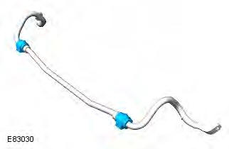
Range Rover Evoque: Rear Stabilizer Bar
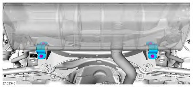
Removal
NOTES:
Some variation in the illustrations may occur, but the essential information is always correct.
Removal steps in this procedure may contain installation details.
1. WARNING: Make sure to support the vehicle with axle stands. Raise and support the vehicle.
2. WARNING: Make sure that a new nut is installed.
CAUTION: Make sure that the ball joint ball does not rotate.
- Torque: 60 Nm
- Repeat the above step for the other side.
3. Torque:
Stage 1: 60 Nm
Stage 2: 60 Nm
4. NOTE: Do not disassemble further if the component is removed for access only. Inspect the component and install a new one if damaged.
Installation
1. To install, reverse the removal procedure.
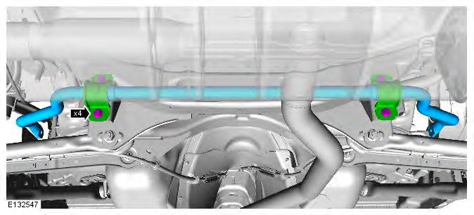
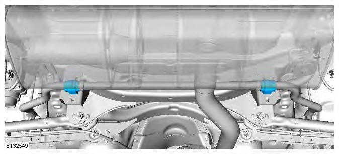
Rear Stabilizer Bar Bushing
Removal
CAUTION: Nuts and bolts must be tightened with the weight of the vehicle on the suspension.
NOTES:
Some variation in the illustrations may occur, but the essential information is always correct.
Removal steps in this procedure may contain installation details.
1. WARNING: Make sure to support the vehicle with axle stands. Raise and support the vehicle.
2. CAUTION: Make sure that new bolts are installed.
Torque:
Stage 1: 60 Nm
Stage 2: 60 Nm
3.
Installation
1. To install, reverse the removal procedure.
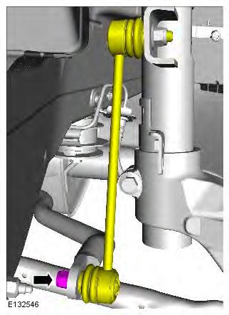
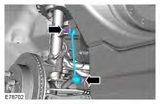
Rear Stabilizer Bar Link
Removal
CAUTION: Nuts and bolts must be tightened with the weight of the vehicle on the suspension.
NOTES:
Some variation in the illustrations may occur, but the essential information is always correct.
Removal steps in this procedure may contain installation details.
1. WARNING: Make sure to support the vehicle with axle stands. Raise and support the vehicle.
2. Refer to: Wheel and Tire (204-04 Wheels and Tires, Removal and Installation).
3. WARNING: Make sure that new nuts are installed.
CAUTION: Make sure that the ball joint ball does not rotate. Torque: 60 Nm
Installation
1. To install, reverse the removal procedure.
READ NEXT:
 Wheel Knuckle
Special Tool(s)
205-857
Remover, Halfshaft
JLR-204-804
Lever, Wheel Knuckle
Removal
CAUTIONS:
Nuts and bolts must be tightened with the weight of the vehicle on the
suspension.
Do not allow halfshaf
Rear Shock Absorber Vehicles Without: Dynamic
Suspension
General Equipment
Suspension Spring Compressor
Vise
Removal
WARNINGS:
Make sure the spring compressor Safe Working Load (SWL) meets or exceeds
the spring rating quoted in the
Specifcations sectio
Shock Absorber and Spring Assembly Vehicles Without:
Dynamic Suspension
Special Tool(s)
JLR-204-804
Lever, Wheel Knuckle
General Equipment
Transmission jack
Wooden Block
CAUTIONS:
Nuts and bolts must be tightened with the weight of the vehicle on the
suspension.
LH
SEE MORE:
Important information
The information contained in this handbook covers all vehicle derivatives and
optional equipment,
some of which may not be fitted to your vehicle. Due to printing cycles, this
handbook may include
descriptions of options before they become generally available.
The vehicle options, hardware an
Symbols used in this handbook
Safety warnings indicate either a procedure which must be followed
precisely, or
information that should be considered with great care, in order to avoid the
possibility
of personal injury.
Cautions indicate either a procedure which must be followed precisely, or
information that
should
