Range Rover Evoque: Shock Absorber and Spring Assembly Vehicles Without: Dynamic Suspension
Special Tool(s)
 JLR-204-804
Lever, Wheel Knuckle
General Equipment
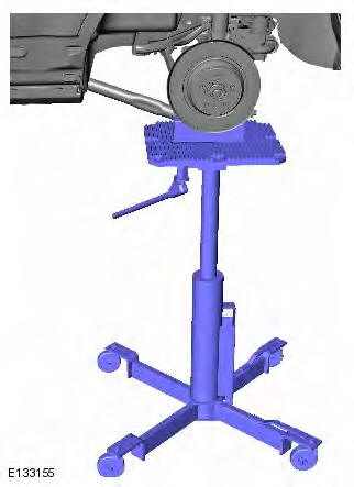
- Transmission jack
- Wooden Block
CAUTIONS:
Nuts and bolts must be tightened with the weight of the vehicle on the suspension.
LH illustration shown, RH is similar.
NOTES:
Removal steps in this procedure may contain installation details.
Some variation in the illustrations may occur, but the essential information is always correct.
1. Refer to: Loadspace Trim Panel (501-05 Interior Trim and Ornamentation, Removal and Installation).
2. WARNING: Make sure to support the vehicle with axle stands. Raise and support the vehicle.
3. Refer to: Wheel and Tire (204-04 Wheels and Tires, Removal and Installation).
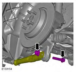
4. WARNING: Make sure that a new nut is installed.
Torque:
Bolts 10 Nm
nut 60 Nm
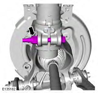
5. Torque: 110 Nm
6. Torque: 270 Nm
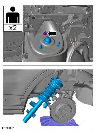
7.
- General Equipment: Transmission jack
- General Equipment: Wooden Block
8. Torque: 175 Nm

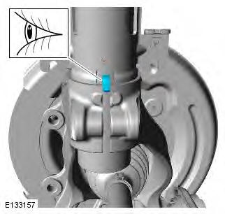
9. CAUTION: Note the fitted position of the component prior to removal.
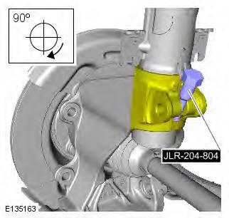
10. Install the Special Tool(s): JLR-204-804
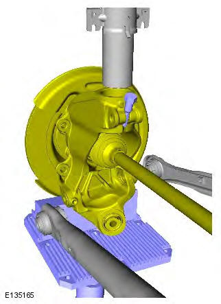
11.
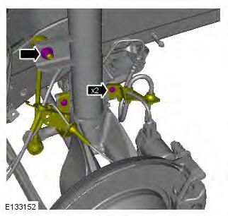
12. Torque: 32 Nm
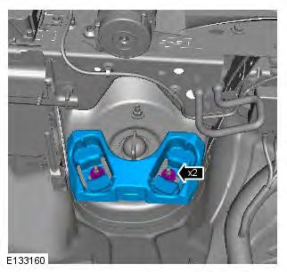
13. Torque: 32 Nm
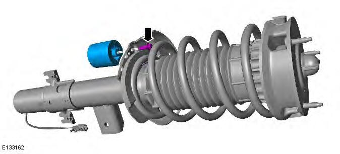
14. NOTES:
Do not disassemble further if the component is removed for access only.
Only if fitted.
Torque: 10 Nm
Installation
1. NOTE: Make sure that the component is installed to the noted removal position. To install, reverse the removal procedure.

READ NEXT:
 Wheel Knuckle Rear Bushing
Special Tool(s)
204-620-01
Installer, Wheel Knuckle Bushing
204-620-02
Remover/Installer, Wheel Knuckle Bushing
204-620-03
Remover, Wheel Knuckle Bushing
LR-121
Hydraulic Cylinder 10t
Removal
1. WARNI
Rear Shock Absorber Vehicles With: Dynamic
Suspension
General Equipment
Suspension Spring Compressor
Vise
Removal
WARNINGS:
Make sure the spring compressor Safe Working Load (SWL) meets or exceeds
the spring rating quoted in the
Specifcations sectio
Shock Absorber and Spring Assembly Vehicles With:
Dynamic Suspension
Special Tool(s)
JLR-204-804
Lever, Wheel Knuckle
General Equipment
Transmission jack
Wooden Block
Removal
CAUTIONS:
Nuts and bolts must be tightened with the weight of the vehicle on the
suspensi
SEE MORE:
Driving in arduous conditions
When a vehicle is operated in extremely
arduous conditions, more frequent attention
must be paid to servicing requirements.
Arduous driving conditions include:
- Driving in dusty and/or sandy conditions.
- Driving on rough and/or muddy roads.
- Frequent wading.
- Frequent driving at high spee
Airbag system
The components that make up
the
airbag system are sensitive to
electrical or physical interference,
either of which could easily damage
the system and cause inadvertent
operation or a malfunction of the
airbag module.
To prevent malfunction of the airbag system
always consult your Dealer/
