Range Rover Evoque: Ride and Handling Optimization
Ride and Handling Optimization AWD
COMPONENT LOCATION
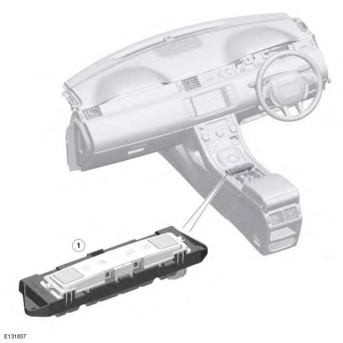
- Terrain Response switchpack and control module
OVERVIEW
The Terrain Response system allows the driver to select a program which aims to provide the optimum settings for traction and performance for the prevailing terrain conditions. The system cannot be switched off. The default program 'special programs off' is an active program that covers all general driving conditions. Three specific terrain programs are selectable to cover all terrain surfaces. Vehicles fitted with the adaptive dynamics suspension also include a special dynamic program.
The system is controlled by a Terrain Response switchpack. The Terrain Response switchpack allows the selection of one of the following five programs:
- Special programs off.
- Grass/Gravel/Snow.
- Mud/Ruts.
- Sand.
- Dynamic (vehicles with adaptive dynamics suspension only).
The instrument cluster displays the selected program in the message center.
The Terrain Response system uses a combination of a number of vehicle sub-systems to achieve the required vehicle characteristics for the terrain selected. The following sub-systems are used in the Terrain Response system:
- EMS (engine management system). For additional information, refer to: Electronic Engine Controls (303-14A Electronic Engine Controls - TD4 2.2L Diesel, Description and Operation), Electronic Engine Controls (303-14B Electronic Engine Controls - GTDi 2.0L Petrol, Description and Operation).
- Automatic transmission (where fitted).
Refer to: External Controls (307-05 Automatic Transmission/Transaxle External Controls - Vehicles With: AWF21 6-Speed Automatic Transmission, Description and Operation).
- Active on-demand coupling. For additional information, refer to: Rear Drive Axle/Differential (205-02, Description and Operation).
- Brake system.
Refer to: Anti-Lock Control - Traction Control - AWD (206-09B Anti-Lock Control - Traction Control, Description and Operation).
- The adaptive dynamics system (where fitted).
Refer to: Vehicle Dynamic Suspension (204-05 Vehicle Dynamic Suspension, Description and Operation).
- The power steering system.
Refer to: Power Steering - AWD (211-02 Power Steering, Description and Operation).
The Terrain Response switchpack also contains the Terrain Response control module. The control module detects the selection made on the switchpack and transmits a signal on the high speed CAN (controller area network) bus, which is received by each of the sub-system control modules. Each of the affected control modules contain software which applies the correct operating parameters to their controlled system for the Terrain Response program selection made. They also provide feedback for the selected program so that the Terrain Response control module can check that all systems have changed to the correct operating parameters.
Information is displayed in the instrument cluster message center which informs the driver of improvements which can be made to the vehicle operating parameters to optimize the vehicle for the prevailing conditions.
Inexperienced off-road drivers may benefit from the automatic assistance of the Terrain Response system and the driver information. Experienced off-road drivers can select the specific programs for extreme conditions to access control over the vehicle systems (for example; accelerator pedal maps, transmission shift maps, traction settings) which are not accessible on vehicles without Terrain Response.
Stop/Start Vehicles
Activation of the Terrain Response special programs will deactivate the stop/start system. However, if a special program is selected while the engine is shutdown in a stop/start cycle, the engine will automatically restart. During the restart sequence, if the stop/start system detects that the driver may not be present, for example either the driver safety belt or door is unlatched, the engine will not restart. The stop/start system will then display the message Restart Required Press Clutch in the message center.
Refer to: Starting System - AWD (303-06A Starting System - TD4 2.2L Diesel, Description and Operation).
System Operation and Component Description
System Operation
PRINCIPLES OF OPERATION
The following vehicle sub-system control modules are used for the Terrain Response system:
- ECM (engine control module)
- TCM (transmission control module) (automatic transmission only)
- Active on-demand coupling module.
- ABS (anti-lock brake system) module.
- ADM (adaptive dynamics module) (where fitted).
- Power steering module.
Each sub-system operates in different ways in relation to the selected Terrain Response program to achieve the optimum traction, stability and ease of control for the terrain encountered.
ENGINE MANAGEMENT SYSTEM
The ECM can change the accelerator pedal maps to change the amount of torque per percentage of pedal travel.
Each terrain program uses a combination of operating parameters for each sub-system. Changing between terrain programs initiates a different set of operating characteristics which will be noticeable to the driver, for example; if the accelerator pedal is held in a constant position and the terrain program is changed from Grass/Gravel/Snow to Sand, the driver will notice the torque and engine speed increase. If the terrain program is changed from Sand to Grass/Gravel/Snow, the driver will notice a reduction in torque and engine speed.
NOTE: The change in torque and engine speed can take approximately 30 seconds and care must be taken not to confuse the Terrain Response system operation with an engine management fault.
TRANSMISSION CONTROL (AUTOMATIC TRANSMISSION ONLY)
The TCM changes the shift maps for the Terrain Response program selected. This changes the shift points providing early or late upshifts and downshifts when compared to special programs off.
For example, in the grass/gravel/snow program, the transmission will perform early upshifts and very late downshifts to ensure the transmission is in the highest gear possible. The hill detection function of the TCM will lock the torque converter and hold whichever gear is selected to the engine speed (rev/min) limit if necessary when descending a steep incline. This provides maximum engine braking before the driver needs to apply the brakes.
Sport mode is only available when special programs off is selected. Sport mode is disabled in all Terrain Response special programs. When S (sport) is selected on the transmission selector in a Terrain Response special program, the transmission will select Command Shift. Sport mode will not be available.
ACTIVE ON-DEMAND COUPLING CONTROL
The active on-demand coupling module has two operating strategies; pre-emptive and reactive.
The pre-emptive strategy anticipates and predicts the locking torque value required to minimize slip and maximize stability. Each Terrain Response program has a different threshold and input criteria for the pre-emptive strategy. For example, a higher locking torque would be applied on slippery surfaces.
The reactive strategy varies the amount of locking torque in response to the actual slip level and the dynamic behavior of the vehicle. Each Terrain Response program has a different threshold and input for the reactive strategy. The reactive strategy improves vehicle traction and composure by eliminating any wheel spin which has occurred after the pre-emptive strategy was applied. The locking response applied is applicable to the terrain program selected. For example, very sensitive on slippery surfaces to provide maximum traction and minimize surface damage.
The locking torque calculations use various signals from other sub-systems, for example, engine torque, accelerator pedal position, selected gear, steering angle, vehicle speed, lateral acceleration, yaw behavior.
The DSC function of the ABS system can override the active on-demand coupling control and reduce any applied locking torque during DSC action.
ABS SYSTEM CONTROL
The ABS module controls several functions and adjusts the operating parameters of these functions to optimize the selected Terrain Response program.
Traction Control
Traction control uses different slip/acceleration thresholds to improve traction and vehicle composure. For example, the system sensitivity is increased on slippery surfaces such as wet grass or snow to reduce wheel spin. If wheel spin was allowed in these circumstances, loss of traction may result from surface damage (wet grass) or the car being unable to move (snow) due to wheel spin.
Dynamic Stability Control
If DSC is switched off (with the DSC switch) when using a Terrain Response special program, if the special program is subsequently changed for a different program, DSC is automatically switched back on.
The DSC uses different threshold values for the selected program to automatically reduce DSC intervention, removing the requirement for the driver to disable the DSC system in order to reduce engine intervention which is sometimes induced in extreme off-road conditions. In extreme sand conditions, there may be an additional benefit of disabling the DSC function using the DSC switch in addition to selecting the sand program.
In the mud/ruts program the DSC system is calibrated to tolerate a higher yaw threshold. This allows a greater differential between the actual and desired wheel turning behavior before DSC intervenes. This allows the DSC system to ignore the effect of ruts 'jarring' the car or adjusting the front wheel steering angle.
The Terrain Response system can alter the balance between engine and brake intervention. For example, when the sand program is selected, the DSC system reduces its reliance on engine intervention and increases the use of brake intervention to maintain the vehicles momentum and prevent it from becoming bogged down if wheel slip is detected.
Hill Descent Control
HDC is automatically switched on or off and target speeds are adjusted in response to the Terrain Response program selected. The responsiveness of the HDC function is also increased where required.
Automatic operation of HDC aims to assist the driver by switching the system on or off when it is of most benefit. HDC is only automatically switched on when the mud/ruts program is selected. HDC is not automatically selected in other programs.
ADAPTIVE DYNAMICS SYSTEM CONTROL
In the special dynamic program, the suspension delivers tighter body control, with flatter handling and sharper responses.
POWER STEERING SYSTEM CONTROL
The power steering module changes the steering maps for the Terrain Response program selected. This will change the active steering (self-centering) and active damping functions of the steering system when compared to special programs off. For example, in sand program the steering will exhibit greater self-centering torque to overcome the increased drag when driving in deep soft sand. This is to reduce the overall driving efforts and provide improved road-wheel feedback characteristics when used in such conditions.
INCORRECT PROGRAM USA
Selection of an inappropriate program is discouraged in the following ways:
- The active program icon is continually displayed in the instrument cluster message center.
- The Terrain Response control module 'locks out' certain functions in some programs, for example:
- Cruise control is only available with the special programs off or grass/gravel/snow program.
- On automatic transmissions, sport mode is deactivated in all special Terrain Response programs. The vehicle will automatically select Command Shift when the vehicle is in a Terrain Response special program.
- When the ignition has been in the off mode continually for more than 6 hours, the Terrain Response system defaults to the special programs off selection.
Selection of an inappropriate program for the terrain conditions will not endanger the driver or cause damage to the vehicle. Continued use of an inappropriate program may reduce the life of some components. The driver may notice reduced vehicle response, with the engine and transmission being less responsive than in special programs off. Also, in some programs, HDC will remain on, signified by illumination of the HDC indicator in the instrument cluster.
DRIVER INFORMATION
The message center in the instrument cluster contains the Terrain Response program icons which display the currently selected program. No symbol is displayed when special programs off is selected.
Any required changes to the sub-systems are also passed to the driver in the form of indicator illumination in the instrument cluster or appropriate messages in the message center, HDC OFF for example.
In certain operating conditions, the Terrain Response system also displays advice or warning messages to ensure the driver is using the vehicle to its full potential, for example, steering angle is displayed in the message center to avoid driving in deep ruts with steering lock applied.
DIAGNOSTICS
The Terrain Response control module stores information on detected Terrain Response faults and CAN (controller area network) errors which can be interrogated using approved diagnostic equipment. The Terrain Response sub-systems and the instrument cluster also store information relating to CAN errors from the Terrain Response control module.
The control module also stores the miles traveled and time elapsed for the individual programs which can also be retrieved using approved diagnostic equipment. This information aids diagnosis of the Terrain Response system and also provides an indication of Terrain Response system abuse by the driver which can lead to premature component failure. This information can also be used to check customer concerns, for example, high fuel consumption which may be due to continued use of a certain program.
TERRAIN RESPONSE SYSTEM FAULT DIAGNOSIS
Terrain response relies on the correct functionality of the sub-systems. If one of the sub-systems develops a fault, the Terrain Response system will not function, even though the fault is not in the Terrain Response system.
It is not possible for the Terrain Response control module to cause any fault behavior (warning indicator illumination or message generation) in any of the sub-systems. Illumination of a sub-system warning indicator and/or a sub-system related message will never be associated with a Terrain Response control module or Terrain Response system fault.
The Terrain Response switchpack should only be investigated if there are no apparent faults in any of the sub-systems. If a fault in a sub-system is subsequently corrected, the Terrain Response system will function normally after an ignition mode 1 and 2 (on and off) cycle.
TERRAIN RESPONSE SUB-SYSTEM FAULTS
When a fault occurs in a sub-system, the driver is alerted by the illumination of a warning indicator and/or an appropriate message for that sub-system in the instrument cluster message center. There will be no warning of a Terrain Response system fault.
When a sub-system fault is present and the driver attempts to select a different Terrain Response program, or at the next ignition mode 2 (on), the message SYSTEM FAULT SPECIAL PROGRAMS NOT AVAILABLE will appear in the message center. This implies that the Terrain Response system has a fault, but only because a sub-system fault is preventing its operation. This message will be displayed for 5 seconds per ignition mode 2 (on) occurrence, but is repeated if a further selection is made by the driver using the Terrain Response switchpack or at the next ignition mode 2 (on) occurrence.
NOTE: The message SYSTEM FAULT SPECIAL PROGRAMS NOT AVAILABLE can also be generated by a fault in the Terrain Response switchpack or control module. Refer to the following information for details of switchpack or control module faults.
It is not possible for the Terrain Response control module to cause any fault behavior (warning indicator illumination or message generation) in any of the sub-systems. Illumination of a sub-system warning indicator and/or a sub-system related message will never be associated with a Terrain Response control module or Terrain Response system fault.
The sub-system control modules can detect a fault with the CAN signal from the Terrain Response control module. If a fault in the Terrain Response system is detected, the sub-system control modules will operate in the special programs off setting. The sub-system control modules will record a fault code for a failure of the Terrain Response CAN signal.
These faults can be retrieved using approved diagnostic equipment and will provide useful information to indicate investigation of the Terrain Response control module or the CAN network.
TERRAIN RESPONSE SWITCHPACK AND CONTROL MODULE FAULTS
If a fault occurs in the Terrain Response switchpack, the amber LED (light emitting diode) in all of the switchpack icons are turned off and program selections are ignored. The instrument cluster message center displays the message SYSTEM FAULT SPECIAL PROGRAMS NOT AVAILABLE when the fault occurs, if the fault is present and the driver attempts to select a special program (if the control module is able to do this) or at the next ignition mode 2 (on).
The Terrain Response switchpack and the control module are an integral unit. If a fault occurs in either component, the whole unit will require replacement. Ensure that the fault is with the Terrain Response control module and not in a sub-system module before replacing the Terrain Response switchpack/control module.
If a CAN fault exists and prevents Terrain Response system operation, all of the Terrain Response switchpack icons are illuminated and program selections are ignored.
If the instrument cluster does not receive a Terrain Response system CAN message from the Terrain Response control module, the message SYSTEM FAULT SPECIAL PROGRAMS NOT AVAILABLE will be displayed when the fault occurs and will be repeated at every ignition mode 2 (on).
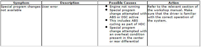
User Error
The following incorrect usage of the system may be misinterpreted as a system fault:
- Engine not running - Program changes and driver advisory messages are only available with the engine running.
- Special program change attempted with DSC or ABS active (this includes ABS cycling which is operational when HDC is being used on slippery or loose surfaces).
- Special program change attempted with overheat condition present on the active on-demand coupling.
Component Description
TERRAIN RESPONSE SWITCHPACK AND CONTROL MODULE
- 5 program Terrain Response
- 4 program Terrain Response
- Left selection switch
- Dynamic program indicator
- Special programs off indicator
- Grass/Gravel/Snow program indicator
- Mud/Ruts program indicator
- Sand program indicator
- Right selection switch
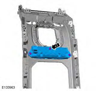
The switchpack and control module is installed in the floor console immediately behind the gear selector. Each program is denoted by a symbol that represents the related terrain. Programs are selected using the left or right selection switch to illuminate the required program indicator.
The switchpack is connected to the vehicle wiring with a harness connector that contains connections for the illumination supply, ignition supply, ground, and high speed CAN bus (positive and negative).
Ride and Handling Optimization
Principles of Operation
Ride and handling optimization incorporates the terrain response system which links a number of modules around the vehicle to give the best combination of settings in the different systems.
For a detailed description of the Ride and Handling System and operation, refer to the relevant Description and Operation section of the workshop manual. REFER to: (204-06 Ride and Handling Optimization)
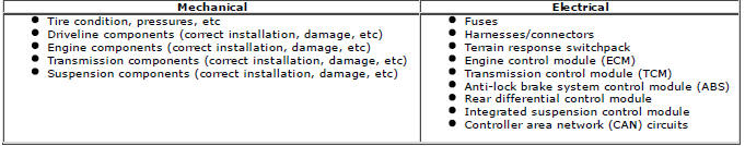
Inspection and Verification
CAUTION: Diagnosis by substitution from a donor vehicle is NOT acceptable. Substitution of control modules does not guarantee confirmation of a fault, and may also cause additional faults in the vehicle being tested and/or the donor vehicle.
NOTE: Check and rectify basic faults before beginning diagnostic routines involving pinpoint tests.
1. Verify the customer concern.
2. Visually inspect for obvious signs of mechanical or electrical damage.
3. Check DDW for open campaigns. Refer to the corresponding bulletins and SSM's which may be valid for the specific customer complaint and carry out the recommendations as needed.
Visual Inspection
4. If an obvious cause for an observed or reported concern is found, correct the cause (if possible) before proceeding to the next step
5. If the cause is not visually evident, verify the symptom and refer to the Symptom Chart.
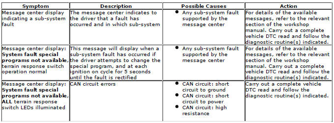
Symptom Chart
Because the overall function of the system is dependent on sub-systems, it is possible to misinterpret displays in the message center as being terrain response faults when they are actually a result of a fault in one of the sub-systems.
Refer to the table below for help in deciding when to investigate terrain response faults and when the fault is likely to be in a sub-system.
DTC Index
For a list of diagnostic trouble codes that could be logged on this vehicle, please refer to Section 100-00.
Ride and Handling Optimization Switch
Removal
NOTE: Removal steps in this procedure may contain installation details.
All vehicles
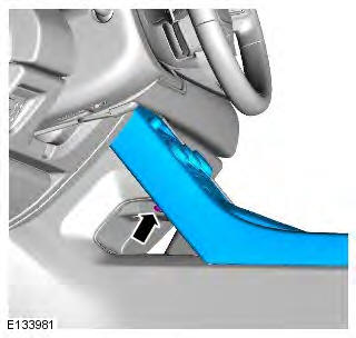
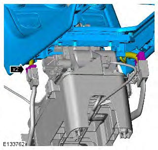
1. CAUTION: LHD illustration shown, RHD is similar.
NOTE: This step must be carried out on both sides.
Torque: 1.9 Nm
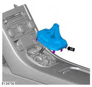
Vehicles with manual transmission
2. Refer to: Gearshift Lever Knob (308-06 Manual Transmission/Transaxle External Controls, Removal and Installation).
3.
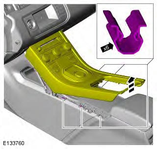
All vehicles
4.
Vehicles with manual transmission
5.
Vehicles with automatic transmission
6.
All vehicles
7. Torque:
M5 bolt 1.5 Nm
Screw 1.1 Nm
8. Torque: 1.1 Nm
Installation
1. To install, reverse the removal procedure.
READ NEXT:
 Driveshaft
Torque Specifications
Driveshaft TD4 2.2L Diesel, Vehicles Without: Diesel
Particulate Filter (DPF)
Removal
1. WARNING: Make sure to support the vehicle with axle stands.
Raise and support the vehicl
SEE MORE:
Transfer Case
Connecting Sleeve Seals TD4 2.2L Diesel, Vehicles With: M66 6-Speed
Manual Transmission AWD
Special Tool(s)
100-012
Slide Hammer
303-1300
Remover, Crankshaft Seal
303-538
Remover/Installer, Crankshaft Oil Seal
307-594
Installer, Seal
307-595
Installer, Intermediate Shaft Seal
308-615
Remover, Seals
Removal
NOTE: Some variation in the illustrations may occur, but the essential
information
Transfer Case Rear
Seal
Special Tool(s)
100-012
Slide Hammer
205-871
Installer, Transfer Case Rear Seal
308-615
Remover, Seals
308-617
Depth Drill, Seal Remover
Removal
NOTES:
Removal steps in this procedure may contain installation details.
Some variation in the illustrations may occur, but the essential information is
