Range Rover Evoque: Vehicle Dynamic Suspension
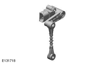
Vehicle Dynamic Suspension - Component Location
COMPONENT LOCATION
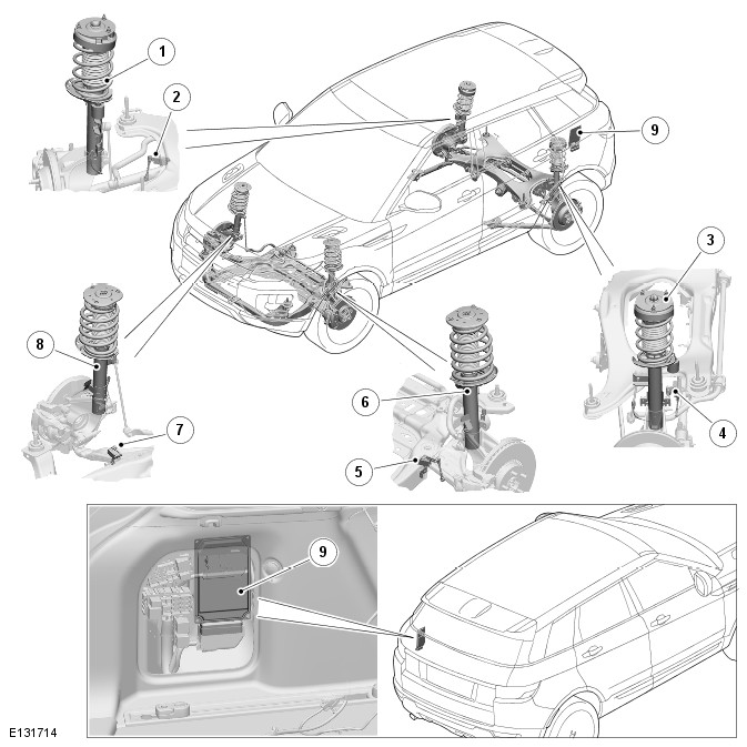
- RH (right-hand) rear spring and damper assembly
- RH rear height sensor
- LH (left-hand) rear spring and damper assembly
- LH rear height sensor
- LH front height sensor
- LH front spring and damper assembly
- RH front height sensor
- RH front spring and damper assembly
- Adaptive damping module
Vehicle Dynamic Suspension - Overview
OVERVIEW
Some vehicles are fitted with an adaptive dynamics system, an electronically controlled suspension system that continuously adjusts the damping characteristics of the suspension dampers in reaction to the current driving conditions.
The system is controlled by the ADM (adaptive damping module). The ADM receives signals from four suspension height sensors and from other vehicle systems to determine vehicle state, body and wheel motions, and driver inputs. These signals are used by the ADM to continuously control the damping characteristics of each damper to the appropriate level, to give the optimum body control and vehicle ride.
Vehicle Dynamic Suspension - System Operation and Component Description
Control Diagram
NOTE: A = Hardwired; D = High speed CAN (controller area network) bus.
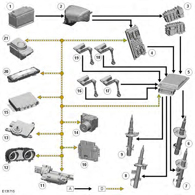
- Battery
- EJB (engine junction box)
- RJB (rear junction box)
- CJB (central junction box)
- ADM
- RH (right-hand) front damper
- RH rear damper
- LH (left-hand) rear damper
- LH front damper
- ECM (engine control module)
- Power steering module
- Instrument cluster
- TCM (transmission control module)
- ABS (anti-lock brake system) module
- Driveline control unit
- LH rear suspension height sensor
- RH rear suspension height sensor
- LH front suspension height sensor
- RH front suspension height sensor
- Terrain response module
- Transmission selector
System Operation
PRINCIPLES OF OPERATION
The ADM uses a combination of information from other system modules and data from the height sensors to measure the vehicle and suspension states and driver inputs. Using this information, the ADM applies algorithms to control the dampers for the current driving conditions.
The ADM receives the following signals on the high speed CAN bus from the stated system components:
- Brake pressure - ABS module.
- Brake pressure quality factor - ABS module.
- Car configuration parameters - CJB.
- Engine speed - ECM.
- Engine speed quality factor - ECM.
- Engine torque flywheel actual - ECM.
- Engine torque flywheel actual quality factor - ECM.
- Gear position target - TCM (automatic transmission vehicles only).
- Lateral acceleration - ABS module.
- Power mode (ignition signal) - CJB.
- Power mode quality factor - CJB.
- Roll stability control mode - ABS module.
- Steering wheel angle - ABS module.
- Steering wheel angle speed - ABS module.
- Steering wheel angle status - ABS module.
- Terrain mode requested - transmission selector (automatic transmission vehicles only).
- Torque converter slip - TCM (automatic transmission vehicles only).
- Vehicle information parameters HS - CJB.
- Vehicle speed - ABS module.
- Vehicle speed quality factor - ABS module.
- Front left wheel speed - ABS module.
- Front left wheel speed quality factor - ABS module.
- Front right wheel speed - ABS module.
- Front right wheel speed quality factor - ABS module.
- Rear left wheel speed - ABS module.
- Rear left wheel speed quality factor - ABS module.
- Rear right wheel speed - ABS module.
- Rear right wheel speed quality factor - ABS module.
The ADM also outputs information on the high speed CAN bus for use by other systems as follows:
- Fault message - instrument cluster.
- Terrain mode change status - transmission selector (automatic transmission vehicles only).
- Terrain mode - transmission selector (automatic transmission vehicles only).
The ADM monitors the input signals and operates the damper solenoids. The input signals are used in control functions and a force required for each damper, for each function, is calculated. An arbitrator monitors the force requirements from each function and apportions a force to a damper. The force is converted to the appropriate current and sent to the damper.
The control functions are as follows:
- Body Control - Uses suspension height sensors and CAN inputs. Calculates road induced body motions 200 times a second and sets each damper to the appropriate level to maintain a flat and level body attitude. Provides improved body control without loss of ride quality.
- Roll Rate Control - Uses CAN inputs. Predicts vehicle roll rate due to driver steering inputs 100 times a second and increases damping to reduce roll rate. Provides improved control and driver confidence.
- Pitch Rate Control - Uses CAN inputs. Predicts vehicle pitch rate due to driver throttle and braking inputs 100 times a second and increases damping to reduce pitch rate. Provides improved control and driver confidence.
- Bump Rebound Control - Uses suspension height sensor and CAN inputs. Monitors the position of the wheel 1000 times a second and increases the damping rate as the damper approaches the end of its travel. Provides improved ride quality.
- Wheel Control - Uses suspension height sensor and CAN inputs. Monitors the position of the wheel 1000 times a second and provides the appropriate level of damping for the suspension velocity.
- Dynamic program -
- Off-road modification -
Under normal road conditions, when the vehicle is stationary with the engine running, the dampers are set to the lowest damping condition to reduce power consumption.
The ADM receives its power supply via a relay and fuse in the CJB. The relay remains energized for a period of time after the ignition is off. This allows the ADM to record and store any DTC (diagnostic trouble code) relating to adaptive dynamics system faults.
Component Description
DAMPERS
NOTE: Rear damper shown, front damper similar.
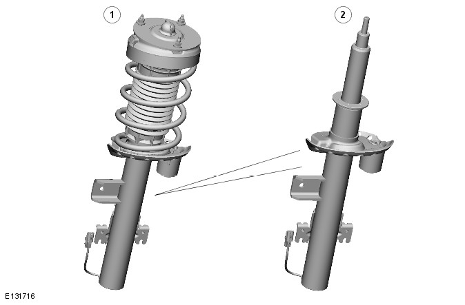
- Damper and spring assembly
- Damper
The adaptive dynamics dampers are inverted monotube dampers that contain a MR (magneto rheological) fluid, i.e. the flow properties of the fluid change when it is subjected to a magnetic field. This allows the damping force to be electrically adjusted to provide the optimum compromise between vehicle control and ride comfort.
The MR fluid consists of suspended iron particles in a base fluid of synthetic hydrocarbon. When the MR fluid is not magnetized, the iron particles are dispersed randomly to give the MR fluid a mineral-oil-like consistency for low damping forces. When the MR fluid is magnetized, the iron particles align to form fibrous structures and make the MR fluid more viscous to increase the damping forces. The MR fluid can change from the mineral-oil-like consistency used for low damping through to a fibrous consistency for high damping forces, depending on the strength of the magnetic field.
The magnetic field is produced by two coils integrated into the damper piston and connected to the ADM via a fly-lead and an external electrical connector. When energized by the ADM, the coils produce magnetic fields in the RM fluid as it flows through passageways in the damper piston from the high pressure side to the low pressure side. The coils are energized by a 30 kHz PWM (pulse width modulation) signal from the ADM. The ADM continuously varies the signals to independently increase and decrease the damping of each damper as required. The current is varied between 0 A (lowest damping force) and 5 A (highest damping force).
Sectioned View of Damper
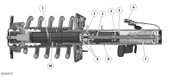
- Dividing piston
- Damper piston
- Rod
- Seal pack
- Bump plate
- Electrical connector
- Spring aid
- Reservoir tube
- Solenoids
- Strut rod
SUSPENSION HEIGHT SENSORS
Four suspension height sensors are used in the adaptive dynamics system, two for the front suspension and two for the rear suspension. A front suspension height sensor is attached to a bracket on each side of the front subframe and connected by a sensor arm and sensor link to the related lower arm of the front suspension. A rear suspension height sensor is attached to a bracket on each side of the rear subframe and connected by a sensor arm and sensor link to the related rear transverse link of the rear suspension. On each suspension height sensor, the sensor arm and sensor link convert linear movement of the suspension into rotary movement of the sensor shaft.
The suspension height sensors are single track units, except on vehicles with automatic headlamp levelling, where the RH sensors are twin track units.
NOTE: Vehicles without adaptive damping, but with automatic headlamp levelling, only have two suspension height sensors, which are single track units installed on the RH side.
The suspension height sensors measure suspension displacement at each corner of the vehicle and output a corresponding analogue signal to the ADM. The algorithms in the ADM calculate the position, velocity and frequency content of the signals and use the results for individual wheel control.
Each suspension height sensor is connected to the ADM via three wires, which supply ground, 5 V supply and signal return.
Each sensing element consists of an array of Hall effect devices arranged to measure the direction of the magnetic field of a small magnet attached to the end of the sensor shaft. As the sensor shaft rotates, so do the lines of magnetic flux from the attached magnet. The signals from each of the Hall effect elements are processed by means of a dedicated integrated circuit, to generate an output voltage that varies as the sensor shaft is rotated. The sensor has a measurement range of +- 40
READ NEXT:
 Ride and Handling Optimization
Ride and Handling Optimization AWD
COMPONENT LOCATION
Terrain Response switchpack and control module
OVERVIEW
The Terrain Response system allows the driver to select a program which aims
to prov
Driveshaft
Torque Specifications
Driveshaft TD4 2.2L Diesel, Vehicles Without: Diesel
Particulate Filter (DPF)
Removal
1. WARNING: Make sure to support the vehicle with axle stands.
Raise and support the vehicl
SEE MORE:
Important information
The information contained in this handbook covers all vehicle derivatives and
optional equipment,
some of which may not be fitted to your vehicle. Due to printing cycles, this
handbook may include
descriptions of options before they become generally available.
The vehicle options, hardware an
Symbols used in this handbook
Safety warnings indicate either a procedure which must be followed
precisely, or
information that should be considered with great care, in order to avoid the
possibility
of personal injury.
Cautions indicate either a procedure which must be followed precisely, or
information that
should
