Range Rover Evoque: Anti-Lock Control - Traction Control AWD
Component Location
NOTE: RHD (right-hand drive) installations shown; LHD (left-hand drive) installations similar.
COMPONENT LOCATION - SHEET 1 OF 2
- RH (right-hand) front wheel speed sensor
- RH rear wheel speed sensor
- LH (left-hand) rear wheel speed sensor
- LH front wheel speed sensor
- Integrated ABS (anti-lock brake system) module and HCU (hydraulic control unit)
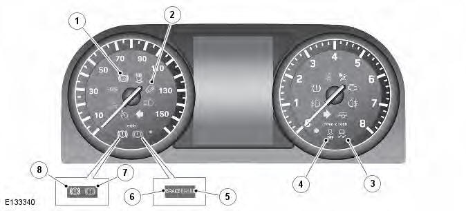
COMPONENT LOCATION - SHEET 2 OF 2
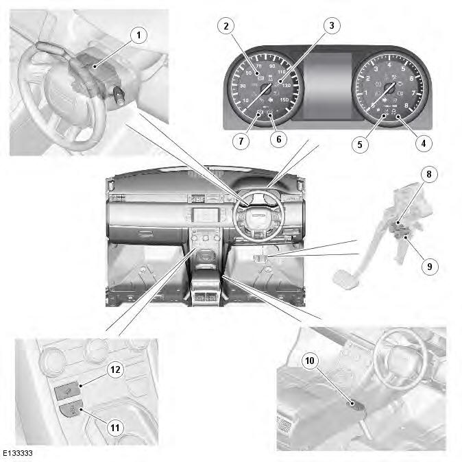
- Steering angle sensor (in clockspring)
- ABS warning indicator
- HDC (hill descent control) active indicator
- DSC (Dynamic Stability Control) warning indicator
- DSC OFF warning indicator
- Brake red warning indicator
- Brake amber warning indicator
- Brake diagnostic switch
- Stoplamp switch
- Yaw rate sensor
- DSC switch
- HDC switch
Overview
OVERVIEW
The anti-lock control - traction control system features an ABS (anti-lock brake system) module attached to a 4-channel HCU (hydraulic control unit). The integrated ABS module and HCU is located in the rear left side of the engine compartment, and is installed in the brake hydraulic circuit between the brake master cylinder and the four brake calipers.
The ABS module is connected to the high speed CAN (controller area network) bus, and actively interacts with other vehicle system control modules and associated sensors to receive and transmit current vehicle operating information.
When required, the ABS module will actively intervene and operate the HCU during braking or vehicle maneuvers to correct the vehicle attitude, stability, traction or speed. During severe incidents of vehicle correction, the ABS module will also request the ECM (engine control module) to reduce engine power in order to further stabilize and correct the vehicle.
To provide full system functionality, the anti-lock control and traction control system includes the following components:
- DSC (dynamic stability control) switch.
- HDC (hill descent control) switch.
- Four wheel speed sensors.
- Yaw rate sensor.
- Steering angle sensor.
- Instrument cluster warning indicators.
- Integrated ABS module and HCU.
The anti-lock control and traction control system also provides the following brake functions that are designed to assist the vehicle or aid the driver:
- ABS.
- CBC (corner brake control).
- DSC (dynamic stability control).
- EBD (electronic brake force distribution).
- ETC (electronic traction control).
- EBA (emergency brake assist).
- EDC (engine drag-torque control).
- HDC (hill descent control), with gradient release control.
- Hill start assist.
- RSC (roll stability control).
- Terrain response system integration.
- Trailer stability assist.
System Operation and Component Description
Control Diagram
NOTE: A = Hardwired; D = High speed CAN (controller area network) bus; O = LIN (local interconnect network) bus; U = Private high speed CAN bus.
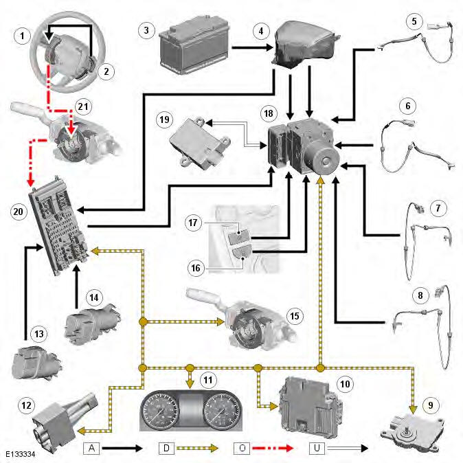
- Steering wheel LH (left-hand) switchpack
- Steering wheel RH (right-hand) switchpack
- Battery
- EJB (engine junction box)
- LH front wheel speed sensor
- RH front wheel speed sensor
- LH rear wheel speed sensor
- RH rear wheel speed sensor
- TCM (transmission control module) (automatic transmission models only)
- ECM (engine control module)
- Instrument cluster
- Diagnostic socket
- Brake diagnostic switch
- Stoplamp switch
- Steering angle sensor
- DSC switch
- HDC switch
- ABS (anti-lock brake system) module
- Yaw rate sensor
- CJB (central junction box)
- Clockspring
System Operation
ANTI-LOCK BRAKE SYSTEM
The ABS controls the speed of all road wheels to ensure optimum wheel slip when braking at the adhesion limit. The wheels are prevented from locking to retain effective steering control of the vehicle.
The front and rear brake pressures are modulated separately for each wheel.
CORNER BRAKE CONTROL
CBC influences the brake pressures, below and within ABS thresholds, to counteract the yawing moment produced when braking in a corner. CBC produces a correction torque by limiting the brake pressure on one side of the vehicle, to assist the vehicle in achieving the turn radius the driver is requesting.
DYNAMIC STABILITY CONTROL
DSC uses brakes and powertrain torque control to assist in maintaining the lateral stability of the vehicle. While the ignition is energized the DSC function is permanently enabled, unless selected off using the DSC switch.
DSC enhances driving safety in abrupt maneuvers and in under-steer or over-steer situations that may occur in a bend. The ABS module monitors the yaw rate and lateral acceleration of the vehicle and the steering input, then selectively applies individual brakes and signals for powertrain torque adjustments to reduce under-steer or over-steer.
In general:
- In an under-steer situation; the inner wheels are braked to counteract the yaw movement towards the outer edge of the bend.
- In an over-steer situation; the outer wheels are braked to prevent the rear end of the vehicle from pushing towards the outer edge of the bend.
The ABS module monitors the tracking stability of the vehicle using inputs from the wheel speed sensors, the steering angle sensor, and the yaw rate sensor. The tracking stability is compared with stored target data. Whenever the tracking stability deviates from the target data, the ABS module intervenes by applying the appropriate brakes.
The following interactions occur in an intervention situation:
- High speed CAN signal to the ECM, to reduce engine torque.
- High speed CAN signal to the active on-demand coupling module, to open the locking torque of the center coupling.
- Application of braking to the appropriate corner of the vehicle.
ELECTRONIC BRAKE FORCE DISTRIBUTION
Only the rear brakes are controlled by the EBD (electronic brake force distribution) function. EBD limits the brake pressure applied to the rear wheels. When the brakes are applied, the weight of the vehicle transfers forwards, reducing the ability of the rear wheels to transfer braking effort to the road surface. This may cause the rear wheels to slip and make the vehicle unstable.
EBD uses the anti-lock braking hardware to automatically optimize the pressure of the rear brakes, below the point where ABS is normally invoked.
ELECTRONIC TRACTION CONTROL
ETC attempts to optimize forward traction by reducing engine torque, or by applying the brake of a spinning wheel until traction is regained.
ETC is activated if an individual wheel speed is above that of the vehicle reference speed (positive slip) and the brake pedal is not pressed. The brake is applied to the spinning wheel, allowing the excess torque to be transmitted to the non-spinning wheels through the drive line. If necessary, the ABS module also sends a high speed CAN bus message to the ECM to request a reduction in engine torque.
When the DSC function is selected off using the DSC switch, the engine torque reduction feature is disabled.
EMERGENCY BRAKE ASSIST
EBA (emergency brake assist) helps the driver in emergency braking situations by automatically maximizing the applied braking effort. There are two situations when the ABS module will invoke EBA:
- When the brake pedal is rapidly pressed.
- When the brake pedal is pressed hard enough to bring the front brakes into ABS operation.
When the brake pedal is rapidly pressed, the ABS module increases the hydraulic pressure to all of the brakes until the threshold for ABS operation is reached. This action applies the maximum braking effort for the available traction. The ABS module monitors for the sudden application of the brakes using inputs from the brake pedal switch and from the pressure sensor within the HCU (hydraulic control unit). With the brake pedal pressed, if the rate of increase of hydraulic pressure exceeds the predetermined limit, the ABS module invokes emergency braking.
When the brake pedal is pressed hard enough to bring the front brakes into ABS operation, the ABS module increases the hydraulic pressure to the rear brakes up to the ABS threshold.
EBA operation continues until the driver releases the brake pedal sufficiently for the hydraulic pressure in the HCU to drop below a threshold value stored in the ABS module.
ENGINE DRAG-TORQUE CONTROL
EDC prevents wheel slip caused by any of the following:
- A sudden decrease in engine torque when the accelerator is suddenly released.
- The sudden engagement of the clutch after a downshift on manual transmission vehicles.
- A downshift using the paddle switch on automatic transmission vehicles.
When the ABS module detects the onset of wheel slip without the brakes being applied, it signals the ECM on the high speed CAN bus to request a momentary increase in engine torque. Also, when the driver is braking and the ABS module has reduced brake pressure, but the wheels have not accelerated to the vehicle reference speed quickly enough, EDC will increase engine torque to accelerate the wheels up to reference speed and regain stability.
HILL DESCENT CONTROL
HDC uses engine braking and brake intervention to control the vehicle speed and acceleration during low speed off-road descents and in low grip on-road conditions. Generally, equal pressure is applied to all four brakes, but pressure to individual brakes may be modified by the ABS and HDC functions to retain vehicle stability. Selection of the HDC function is controlled by the HDC switch located on the floor console. HDC operates at vehicle speeds up to 50 km/h (31 mph).
WARNING: Incorrect use of the HDC function may compromise the stability of the vehicle, resulting in a dangerous and uncontrolled hill descent. Pressing the clutch pedal and/or driving with the transmission in neutral while HDC is active, will prevent engine braking from assisting the vehicle. The brakes will overheat and induce the HDC fade out strategy. In this condition there will be no control over the vehicle during a descent.
NOTE: With the HDC function selected, HDC is operative even when the clutch pedal is pressed or the transmission is in neutral. It is not recommended to drive the vehicle further than is absolutely necessary with HDC selected, and the clutch pedal pressed or the transmission in neutral.
On manual transmission vehicles, HDC may be used in first, second and reverse gears only. Once the vehicle is moving, the clutch pedal is to be fully released. The vehicle is not recommended to be driven with HDC active and the transmission in neutral.
On automatic transmission vehicles, HDC may be used in D (drive), R (reverse) and gears 1 and 2 in sport mode. When in D, the TCM will automatically select the most appropriate gear. It is not recommended to drive the vehicle with HDC active and the transmission in N (neutral).
HDC can be selected at any speed, but will only be enabled at speeds below 50 km/h (31 mph).
When HDC is selected:
- At speeds up to 50 km/h (31 mph), the HDC active indicator is permanently illuminated if a valid gear is selected.
- At speeds above 50 km/h (31 mph), the HDC active indicator flashes and a message advising that the speed is too high is displayed in the message center.
When HDC is enabled, the driver decides upon a target speed. Initially a default target speed is adopted, then, in any valid gear, the driver can adjust this target speed using the cruise control buttons. The new selected target speed will be indicated to the driver on the HDC display in the message center. The HDC function then compares this target speed with the actual vehicle speed. The ABS module then operates the HCU in the active braking mode as required, to achieve and maintain the target speed. Operation of the vehicle stoplamps during HDC is controlled by the CJB.
Applying the foot brake during active braking may result in a pulse being felt through the brake pedal.
The target speed can be varied between minimum and maximum values for each gear and transmission range, depending on driver inputs through the cruise control buttons. If no cruise control buttons are pressed the ABS module adopts the appropriate default target speed:
HDC Target Speeds
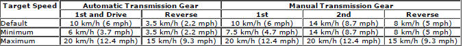
The target speed is varied between the minimum and maximum values using the speed control '+' and '-' buttons. If the driver brakes during HDC control, the driver generated brake pressure supplements the deceleration and the vehicle will slow further. When the brake pedal is released the previously adopted target speed will be used once again. When the driver presses the accelerator pedal the vehicle will accelerate normally and HDC will not intervene; as soon as the driver releases the accelerator pedal the pre-selected target speed will be maintained once more.
During changes of target speed, the ABS module limits vehicle deceleration and acceleration to -0.5 m/s2 (-1.64 ft/s2) and +0.5 m/s2 (+1.64 ft/s2) respectively.
To provide a safe transition from active braking to brakes off, the ABS module invokes a fade out strategy that gradually releases the braking effort during active braking. The fade out strategy occurs if any of the following conditions is detected during active braking:
- HDC is selected off using the HDC switch.
- Failure of a component used by HDC, but not critical to the fade out function.
- Brake overheat.
If fade out is invoked because of HDC de-selection or component failure, the HDC function is cancelled by the ABS module.
If fade out is invoked because of brake overheat, the HDC function remains in standby and resumes operation when the brakes have cooled.
The fade out strategy increases the target speed at a constant acceleration rate of 0.5 m/s2 (1.64 ft/s2), until the maximum target speed is reached, or until no active braking is required for 0.5 second. If the accelerator pedal is positioned within the range that influences target speed, the acceleration rate is increased to 1.0 m/s2 (3.3 ft/s2).
When fade out is invoked because of component failure, a warning chime is sounded and the HDC active indicator is extinguished. A message advising of the fault is displayed in the message center.
When fade out is invoked because of brake overheat, a message advising that HDC is temporarily unavailable is displayed.
At the end of fade out, the HDC active indicator flashes. The flashing active indicator lamp and displayed message continue while HDC remains selected, until the brakes have cooled.
To monitor for brake overheat, the ABS module monitors the amount of braking activity and, from this, estimates the temperature of each brake. If the estimated temperature of any brake exceeds a preset limit, the ABS module invokes the fade out strategy. After a fade out cycle, the HDC function is re-enabled when the ABS module estimates that all of the brake temperatures are at less than 64% of the preset temperature limit.
Gradient Release Control
Gradient release control is an automatic system which is always available when HDC is selected.
If the vehicle is brought to a standstill on a slope using the foot brake, gradient release control will become active (except in the terrain response, sand program).
When descending a hill, a brake hold and gradual release is employed to provide a smooth transition into HDC. Gradient release control operates in forward and reverse gears and requires no driver intervention.
Activation of Stoplamps
Operation of the vehicle stoplamps during HDC is controlled by the CJB. The ABS module monitors the brake system hydraulic pressure and requests the CJB, via the high speed CAN bus, to energize the stoplamps during active braking.
A pressure threshold and time filter prevents the stoplamps from flickering while HDC is braking.
Stop/Start Vehicles
Activation of HDC will deactivate the stop/start system. If HDC is activated while the engine is shutdown in a stop/start cycle, the engine will automatically restart. However, if the stop/start system cannot detect the driver, for example either the driver safety belt or the driver door is unlatched, the engine will not restart. The stop/start system will then request the driver to depress the clutch, to restart the engine, by displaying an appropriate message in the message center. The driver must respond to this request within a limited time period, otherwise a conventional engine restart using the engine START/STOP switch will be required.
HILL START ASSIST
Regardless of HDC selection, the automatic hill start assist function will aid smooth transition from foot brake release to moving away, on all ascents above a 5% gradient. It does this by holding driver generated brake pressure for a short period of time (2-3 seconds) and then balancing brake torque with the propulsion torque generated when the accelerator pedal is applied, to ensure the vehicle does not roll backwards.
ROLL STABILITY CONTROL
The RSC function uses the brakes and the engine to attempt to restore vehicle stability if the vehicle is forced into a harsh maneuver that risks it tipping over.
The ABS module monitors driver inputs and vehicle behavior using various powertrain signals and inputs of wheel speed, steering angle, yaw rate, roll rate and lateral acceleration. These inputs are compared with modeled behavior and, if the vehicle behavior reaches a given risk level, the ABS module cuts the engine power, or brakes one or more wheels sufficiently to allow the vehicle to regain stability and help the driver remain in control.
While the ignition is energized, RSC is permanently enabled even if the DSC function is selected off.
TERRAIN RESPONSE SYSTEM INTEGRATION
The terrain response function integrates the ABS and other vehicle system control modules to assist the vehicle when driving off-road or during difficult surface conditions. Terrain response is activated when a terrain response special program is selected.
When a terrain response special program is activated, the ABS module, along with other vehicle system control modules, will operate in accordance with programmed software maps. The software maps allow the ABS system to function with a threshold that will assist the selected terrain response special program.
Refer to: Ride and Handling Optimization - AWD (204-06 Ride and Handling Optimization, Description and Operation).
TRAILER STABILITY ASSIST
When the trailer electrical socket is connected, the trailer stability assist function operates automatically to enhance the existing DSC and terrain response functions of the vehicle when towing. The system detects sway movements caused by trailer oscillations at speeds in excess of 50 km/h (31 mph) and acts to eliminate them. It does this through braking and engine management. Braking the vehicle asymmetrically counterbalances the sway movement, thereby slowing the vehicle and eliminating the oscillations. Engine management adapts engine torque output to support the braking management in stabilizing the vehicle and trailer.
Typical conditions when sway can occur include:
- Changing highway lanes.
- Traversing a lengthy bend.
- Acceleration.
- Braking.
- Incorrectly laden trailers.
The capability of trailer stability assist to respond early to the beginning of trailer-sway makes the system almost unnoticeable under normal driving conditions and keeps the vehicle and trailer under safe control. Trailer stability assist requires no input from the driver and operates up to the maximum vehicle speed.
Trailer stability assist will not operate while DSC is switched off.
Component Description
DYNAMIC STABILITY CONTROL SWITCH
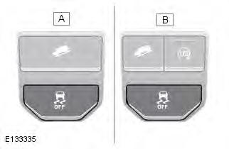
- Vehicles without stop/start system
- Vehicles with stop/start system
The DSC switch is a non-latching switch installed in the floor console, forward of the gear selector. Pressing the DSC switch connects an ignition power feed to the ABS module. With the first press of the DSC switch, the ABS module disables the DSC functions. When the DSC switch is pressed again, the ABS module re-enables the DSC functions. The DSC switch must be pressed for a minimum of 0.3 second for the ABS module to react. The DSC function is re-enabled at the beginning of each ignition cycle.
To confirm that the DSC function is selected off, the amber colored DSC OFF warning indicator in the instrument cluster is continuously illuminated. A message is also displayed in the message center to confirm that DSC is selected off. When the DSC function is selected on again, the DSC OFF warning indicator and message go off.
Although Land Rover recommend that DSC is selected on for all normal driving conditions, it may be beneficial to deselect DSC in order to maximize traction under the following conditions:
- To rock the vehicle out of a hollow or a soft surface.
- When driving on loose surfaces or with snow chains installed.
- When driving in deep sand, snow or mud.
- When driving on tracks with deep longitudinal ruts.
Even when DSC is deselected, driving maneuvers with extreme yaw or lateral acceleration may trigger RSC activity to assist the vehicle stability.
To prevent mis-use of, or in the event of a broken DSC switch, a DTC (diagnostic trouble code) is stored in the ABS module memory if the input from the DSC switch is held high for more than 1 minute.
HILL DESCENT CONTROL SWITCH
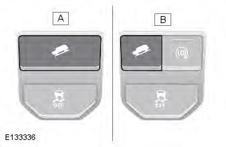
- Vehicles without stop/start system
- Vehicles with stop/start system
The HDC switch controls the selection of the HDC function.
The HDC switch is a non-latching switch installed in the floor console, forward of the gear selector. Momentarily pressing and releasing the HDC switch connects an ignition power feed to the ABS module. With the first press and release of the HDC switch, the ABS module enables operation of the HDC function. When the HDC switch is pressed and released again, the ABS module disables operation of the HDC function.
To prevent mis-use of, or in the event of a broken HDC switch, if the switch is pressed for more than 10 seconds no change of state occurs. A DTC is stored in the ABS module memory if the input from the HDC switch is held high for more than 1 minute.
WHEEL SPEED SENSORS
- Retaining screw
- Wheel speed sensor
- Bearing seal and magnetic encoder ring
- Wheel bearing
- Wheel hub
An active wheel speed sensor is installed in each wheel knuckle, and provides the ABS module with a rotational speed signal from each road wheel. The head of each wheel speed sensor is positioned close to a magnetic encoder incorporated into the seal of the wheel bearing. Each front axle bearing encoder contains 46 north and south pole pairs; each rear axle bearing encoder contains 48 pole pairs. A fly lead connects each sensor to the vehicle harness.
The wheel speed sensor is supplied with a power supply and a signal connection from the ABS module. When the ignition switch is in power mode 6 (ignition), the ABS module supplies power to the wheel speed sensors and monitors the return signals. Rotation of the wheels induces current fluctuations in the speed sensor return signals. The ABS module subsequently converts the return signals into individual wheel speeds and the overall vehicle speed.
The ABS module outputs the individual wheel speeds and the overall vehicle speed on the high speed CAN bus for use by other systems. The quality of the vehicle speed signal is also broadcast on the high speed CAN bus. If all wheel speed signals are available to calculate vehicle speed from, the quality of the vehicle speed signal is set to 'data calculated within specified accuracy'. If one or more wheel speed sensors are inoperative, the quality of the vehicle speed signal is set to 'accuracy outside specification'.
The ABS module monitors the wheel speed sensor circuits for faults. If a fault is detected the ABS module stores a related DTC in memory and illuminates the appropriate brake warning indicators, depending on the system functions affected. A warning chime is also sounded to alert the driver to the fault condition and, if the fault affects the HDC function, a message is displayed in the message center.
As the wheel speed sensors are active devices, a return signal is available when the road wheels are not rotating. This enables the ABS module to check the condition of the speed sensors while the vehicle is stationary.
YAW RATE SENSOR
The yaw rate sensor is located on the floor tunnel, under the front of the floor console. The sensor is secured by three nuts and connects to the vehicle wiring via a multipin connector.
When the ignition is on, the sensor receives a power feed from the CJB. The sensor measures the yaw rate, roll rate, longitudinal acceleration and lateral acceleration of the vehicle, providing values to the ABS module via a dedicated, private high speed CAN bus connection. The ABS module broadcasts these values on the high speed CAN bus for use by other systems.
If a sensor fault is detected by the ABS module, a warning message will be displayed in the instrument cluster message center and the DSC warning indicator will illuminate.
STEERING ANGLE SENSOR
- Steering wheel module
- Clockspring and steering angle sensor
The steering angle sensor is integrated into the clockspring, which is part of the steering wheel module.
The steering wheel module is mounted to the upper steering column with two screws, and receives an electrical supply from the main harness via a multipin connector located on the side of the unit. The module provides the location and electrical connection for the two multifunction switches.
Input signals from the steering angle sensor are received and processed by the steering wheel module to calculate the steering wheel angle, and steering wheel angle speed. The information, together with signal integrity information, is transmitted on the high speed CAN bus for use by the ABS module and functions such as DSC (dynamic stability control).
A code wheel and 16 optical digital sensors are installed inside the steering angle sensor. Rotation of the code wheel is read by the optical digital sensors to produce steering wheel rotational speed signals. The steering angle sensor is able to measure a rotation range of +/-720 degrees, although the steering mechanism will only allow the steering wheel to rotate a maximum of +/-540 degrees.
If a fault occurs within the steering angle sensor, a DTC will be set and stored in the steering angle sensor memory. The steering angle sensor fault is also stored in the ABS module memory. The ABS module will also illuminates the appropriate warning indicators, depending on the brake functions affected. A warning chime is also sounded to alert the driver to the fault condition and, if the fault affects the HDC function, a message is displayed in the message center.
The steering angle sensor and ABS module can be interrogated using Land Rover approved diagnostic equipment.
BRAKE WARNING INDICATORS
- ABS warning indicator
- HDC active indicator
- DSC warning indicator
- DSC OFF warning indicator
- Brake red warning indicator (USA only)
- Brake amber warning indicator (USA only)
- Brake red warning indicator (all except USA)
- Brake amber warning indicator (all except USA)
The instrument cluster contains various warning indicators for the anti-lock control - traction control functions. The warning indicators provide a visual indication of either a system fault or system operating status.
ANTI-LOCK BRAKE SYSTEM MODULE
- ABS module
- HCU
The ABS module controls the brake functions by operating the HCU to modulate hydraulic pressure to the individual wheel brakes.
The ABS module is attached to the HCU and forms an integral component. A multipin connector provides the electrical interface between the ABS module and the vehicle wiring. The ABS module may be interrogated using Land Rover approved diagnostic equipment.
HYDRAULIC CONTROL UNIT
The HCU is a four channel unit that modulates the supply of hydraulic pressure to the brakes, under the control of the ABS module.
The master cylinder primary and secondary circuit outlets are connected to the HCU primary and secondary circuits.
Refer to: Hydraulic Brake Actuation - LHD AWD/RHD AWD (206-06 Hydraulic Brake Actuation, Description and Operation).
Each of the HCU circuits contains the following components to control the supply of hydraulic pressure to the brakes:
- A normally open, solenoid-operated pilot valve, to enable active braking.
- A normally closed, solenoid-operated priming valve, to connect the brake fluid reservoir to the dual circuit hydraulic pump during active braking.
- A hydraulic pump, to generate hydraulic pressure for active braking and return brake fluid to the reservoir.
- Normally open, solenoid-operated inlet valves and normally closed, solenoid-operated outlet valves, to modulate the hydraulic pressure in the individual brakes.
- An accumulator and a relief valve, to allow the fast release of pressure from the brakes.
- Filters, to protect the internal components from contamination.
A pressure sensor in the primary circuit provides the ABS module with hydraulic pressure signals.
Contact pins on the HCU mate with contacts on the ABS module to provide the electrical connections from the ABS module to the dual circuit hydraulic pump motor and the pressure sensors. The solenoids that operate the valves are installed within the ABS module.
Hydraulic Control Unit Schematic Diagram
- Brake booster
- Primary hydraulic circuit
- Secondary hydraulic circuit
- Pulsation damper
- Pulsation damper
- HCU
- Damping chamber
- Dual circuit hydraulic pump
- DC (direct current) motor
- Solenoid-operated pilot valve (2 off)
- Solenoid-operated priming valve (2 off)
- Check valve
- Low-pressure accumulator (2 off)
- Solenoid-operated inlet valve (RH rear brake)
- Solenoid-operated inlet valve (LH front brake)
- Solenoid-operated outlet valve (LH front brake)
- Solenoid-operated outlet valve (RH rear brake)
- Pressure sensor (5 off)
- LH front brake (secondary circuit)
- RH rear brake (secondary circuit)
- LH rear brake (primary circuit)
- RH front brake (primary circuit)
- Solenoid-operated outlet valve (RH front brake)
- Solenoid-operated outlet valve (LH rear brake)
- Solenoid-operated inlet valve (LH rear brake)
- Solenoid-operated inlet valve (RH front brake)
The HCU features 3 operating modes:
- Normal braking / EBD.
- ABS braking.
- Active braking.
Normal Braking / EBD Mode
Initially, all of the solenoid-operated valves are de-energized. Operating the brake pedal produces a corresponding increase or decrease of pressure in the brakes, through the open pilot valves and inlet valves. If the ABS module determines that EBD is necessary, it energizes the inlet valves for both the rear brakes, to isolate the brakes from any further increase in hydraulic pressure. Only the rear brakes are controlled by the EBD function.
ABS Braking Mode
If the ABS module determines that ABS braking is necessary, it energizes the inlet and outlet valves of the related brake and starts the hydraulic return pump. The inlet valve closes to isolate the brake from pressurized fluid; the outlet valve opens to release pressure from the brake into the accumulator and the return pump circuit. The reduced hydraulic pressure allows the wheel to accelerate. The ABS module then operates the inlet and outlet valves to modulate the pressure in the brake to apply the maximum braking effort without locking the wheel. Control of the valves for each wheel takes place individually.
Active Braking Mode
The active braking mode is used to generate and control hydraulic pressure to the brakes for functions other than the normal / EBD and ABS braking modes.
For active braking, the ABS module energizes the pilot valves and priming valves, starts the return pump and energizes all of the inlet valves. Brake fluid, drawn from the reservoir through the master cylinder and priming valve, is pressurized by the hydraulic pump and supplied to the inlet valves. The ABS module then operates the inlet valves and outlet valves, as required, to modulate the pressure in the individual brakes. Some noise may be generated during active braking.
Service Information
The ABS module and HCU form a single component and must not be separated. The ABS module and HCU assembly is supplied in a pre-filled state. After installation, the hydraulic brake system only requires a conventional bleed of the system; there is no requirement to pressure bleed the system.
Anti-Lock Control - Traction Control
Principles of Operation
For a detailed description of the Anti-lock Braking System (ABS), refer to the relevant Description and Operation section in the workshop manual. REFER to: (206-09B Anti-Lock Control - Traction Control)
Inspection and Verification
CAUTION: Diagnosis by substitution from a donor vehicle is NOT acceptable. Substitution of control modules does not guarantee confirmation of a fault, and may also cause additional faults in the vehicle being tested and/or the donor vehicle.
NOTE: Prior to any testing or inspection, the vehicle should be check for any relevant warning lamps being illuminated. If a warning lamp is illuminated, check for DTCs and refer to the relevant DTC Index, if no warning lamp is illuminated, continue with diagnostic procedures below.
1. Verify the 1. customer concern.
2. Visually inspect for obvious signs of damage and system integrity.
Visual Inspection
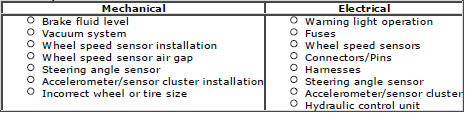
3. If an obvious cause for an observed or reported concern is found, correct the cause (if possible) before proceeding to the next step
4. If the cause is not visually evident, check the anti-lock braking system and steering rotation sensor modules for DTCs (DTCs) and refer to the relevant DTC Index.
Pinpoint Tests
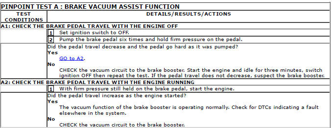
For a complete list of all Diagnostic Trouble Codes (DTCs) that could be logged on this vehicle, please refer to Section 100-00.
REFER to: Diagnostic Trouble Code (DTC) Index - DTC: Anti-lock Braking System (ABS) (100-00 General Information, Description and Operation).
READ NEXT:
 Anti-Lock Control - Traction
Control FWD
Anti-Lock Control - Traction
Control FWD
Component Location
NOTE: RHD (right-hand drive) installations shown; LHD (left-hand drive)
installations similar.
COMPONENT LOCATION - SHEET 1 OF 2
RH (right-hand) front wheel speed sensor
RH rea
Anti-Lock Control - Stability Assist
Accelerometer
Removal
NOTES:
Removal steps in this procedure may contain installation details.
LHD illustration shown, RHD is similar.
Vehicles with automatic transmission
1. Refer to: Floor Console
SEE MORE:
Important information
The information contained in this handbook covers all vehicle derivatives and
optional equipment,
some of which may not be fitted to your vehicle. Due to printing cycles, this
handbook may include
descriptions of options before they become generally available.
The vehicle options, hardware an
Symbols used in this handbook
Safety warnings indicate either a procedure which must be followed
precisely, or
information that should be considered with great care, in order to avoid the
possibility
of personal injury.
Cautions indicate either a procedure which must be followed precisely, or
information that
should
