Range Rover Evoque: Component Description
LEFT STEERING COLUMN MULTIFUNCTION SWITCH
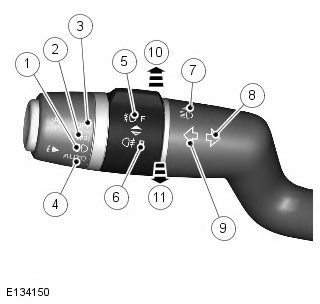
- Off position
- Side lamps position
- Headlamps position
- AUTO - Automatic headlamps position (if fitted)
- Front fog lamps switch
- Rear fog lamps switch
- High beam
- Right turn signal indicator
- Left turn signal indicator
- High beam position
- High beam flash
Left Steering Column Multifunction Switch
The left steering column multifunction switch allows the following selections:
- All exterior lamps off
- Side lamps on
- Headlamps on
- Automatic headlamps active
- Headlamp low/high beam
- Headlamp high beam flash
- Left/right turn signal indicator lamps
- Front/rear fog lamps
- Trip computer functions.
The multifunction switch positions are all connected via a resistive ladder. The output from the resistive ladder is connected to the clockspring which converts the switch operation to LIN bus signals. The signals are received by the CJB which operates the required exterior lighting selection.
Fog Lamps
The fog lamps are controlled by a rotary, non-latching switch on the left steering column multifunction switch. The switch is a momentary switch in both positions for front and rear fog lamps. The front and rear fog lamps can be selected individually. Movement of the switch in either direction will activate or deactivate the selected fog lamps. When active, the fog lamps will remain on until deselected using the fog lamp switch or the headlamps are switched off or when the ignition is in auxiliary power mode 4. The applicable instrument cluster warning indicators will illuminate when the fog lamps are active.
Automatic Headlamps
The (AUTO) automatic headlamp function is a driver assistance system. The driver can override the system operation by selection of side lamp or headlamp on.
The automatic headlamp system uses a rain/light sensor which is connected to the CJB via a LIN bus. The CJB reacts to the signals from the rain/light sensor and activates the exterior lamps as required.
The light sensor is incorporated in the rain/light sensor located on the inside of the windshield, below the rear view mirror.
The wiper system also uses the rain/light sensor for automatic wiper operation.
Refer to: Wipers and Washers (501-16 Wipers and Washers, Description and Operation).
The light sensor measures the ambient light around the vehicle in a vertical direction and also the angular light level from the front of the vehicle. The rain/light sensor uses vehicle speed signals, wiper switch position and the park position of the front wipers to control the system.
The automatic headlamp operation uses ambient light levels which are monitored by photodiodes incorporated in the rain/light sensor. The rain/light sensor sends a lights-on/off request to the CJB on the LIN bus, which responds by switching on or off the low beam headlamps, front side lamps, license plate lamps and rear tail lamps. The automatic headlamps are activated under the following conditions:
- Twilight
- Darkness
- Rain
- Tunnels
- Underground or multistoried car parks.
Operation of the automatic headlamps requires the ignition to be on (power mode 6), the left steering column multifunction switch to be in the 'AUTO' position and a lights on request signal from the light sensor. When the 'AUTO' system is active, the side lamp warning indicator in the instrument cluster will be illuminated.
High Beam On and Flash Functions
The high beam is operated by pushing the left steering column multifunction switch towards the instrument panel. The switch will latch in the high beam position. When the high beam headlamps are active, the high beam warning indicator will illuminate in the instrument cluster.
The high beam flash function is operated by pulling the left steering column multifunction switch away from the instrument panel. The non-latching switch will operate the high beam headlamps for as long as the switch is held. The switch will return to the high beam off position when released. The high beam warning indicator will illuminate when the high beam headlamps are active.
High beam can also be automatically operated by the Auto High Beam (AHB) system (when fitted).
Turn Signal Indicators
The left and right turn signal indicators are operated by moving the left steering column multifunction switch up or down to select right or left turn signal indicators respectively, The switch will latch in each position.
The switch has a turn signal indicator lane change function which is configurable by the dealer. If the switch is gently pushed, but not latched, to either turn signal indicator position and then released, the applicable turn signal indicators will flash 3 times and then will be automatically cancelled.
If a turn signal indicator fails, the green turn signal warning indicator in the instrument cluster will flash at twice the normal rate and the audible ticking from the instrument cluster sounder will also be at twice the normal rate.
Side Lamps and Headlamps
The side lamps and headlamps are selected by a rotary switch on the left steering column multifunction switch.
Rotating the switch from the off position to the side lamps position illuminates the front side lamps, the tail lamps, the license plate lamps and the instrument panel illumination.
Rotating the switch to the headlamps position, switches on the headlamps in addition to the lamps illuminated by the side lamp position.
Auto Headlamps
Auto headlamps is selected by rotating a rotary switch on the left steering column multifunction switch to the 'AUTO' position. When the lighting control switch is in the 'AUTO' position, a reference voltage from the CJB flows through 4 resistors in the lighting control switch. The returned signal voltage is detected by the CJB which activates the auto headlamp function to activate the headlamps and front and rear side/tail lamps.
The rain/light sensor receives a battery voltage output from the ignition relay in the CJB. The rain/light sensor continually outputs a LIN bus message to the CJB with information regarding the ambient light levels. When the ambient light level reaches a predetermined value, the CJB activates the auto headlamps feature. The CJB can also activate the auto headlamps when it receives information regarding rain fall from the rain/light sensor which subsequently activates the auto wipers function.
Trip Computer
For details of the trip computer function refer to Information and Message Center.
Refer to: Information and Message Center (413-08 Information and Message Center, Description and Operation).
HEADLAMP ASSEMBLY
Three headlamp variants are available depending on model specification; halogen, xenon and xenon with Adaptive Front lighting System (AFS).
The headlamps are sealed units, with scratch resistant polycarbonate lenses bonded to the headlamp body. One sealed access cover and a sealed bulb holder provide a watertight environment for the headlamp internal components. To prevent fogging of the lens and to allow the headlamp unit to 'breath' in response to internal temperature changes, a vent is located at the outer rear face of the headlamp body. The vent is covered by a Gortex waterproof membrane. This allows ventilation of the headlamp while preventing the ingress of water.
Each headlamp has one access cover at the rear and a turn signal indicator bulb holder. Access to the cover and/or bulb holder requires removal of the grille and headlamp screws. A release lever at the rear of the headlamp allows the headlamp assembly to be released from its guide slots in the headlamp mounting bracket and moved forwards to allow access to the cover and the turn signal indicator bulb. The cover is removed by rotating clockwise to allow access to the xenon or halogen bulb.
On NAS vehicles, the side marker lamp LED (light emitting diode) is colored orange. The side marker lamp lens is designed so that light from the LED also illuminates the orange colored side marker reflector area at the side of the lamp without the need for an additional bulb.
Xenon Headlamp
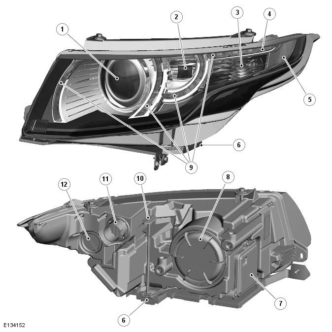
- Projector module - low/high beam headlamp
- Static bending lamp (Not NAS)
- Turn signal indicator
- Side marker lamp LED (NAS only)
- Amber side reflector (NAS only)
- Headlamp mounting bracket
- Xenon control module
- Xenon bulb access cover
- Side lamp/Daytime Running Lamp (DRL) LED
- Release lever
- Electrical connector
- Turn signal indicator bulb holder
A xenon projector module is fitted and operates as a low and high beam unit.
Safety Precautions
The following safety precautions must be followed when working on the xenon headlamp system:
- DO NOT attempt any procedures on the xenon headlamps when the lights are switched on
- Handling of the D3 Xenon bulb must be performed using suitable protective equipment, e.g. gloves and goggles
- The glass part of the bulb must not be touched
- Xenon bulbs must be disposed of as hazardous waste
- Only operate the lamp in a mounted condition in the reflector.
WARNING: The Xenon system generates up to 28000 volts and contact with this voltage could lead to fatality. Make sure that the headlamps are switched off before working on the system.
Headlamp Construction and Functionality - Xenon
The xenon lamp or High Intensity Discharge (HID) lamp as they are sometimes called, comprises an ellipsoidal lens with a solenoid controlled shutter to change the beam output from low to high beam.
The xenon headlamp system is controlled by the CJB using a xenon bulb control module for each headlamp and an xenon bulb igniter. The control modules and the igniters provide the regulated power supply required to illuminate the xenon bulbs through their start-up phases of operation.
The xenon headlamp is a self-contained unit located within the headlamp assembly. The unit comprises a reflector, the lens, a shutter controller and the xenon bulb, which as an assembly is known as the projector module.
The reflector provides the mounting for the xenon bulb which is an integral part of the igniter. The igniter locates in an aperture at the rear of the reflector and is secured with 2 Torx screws to ensure correct alignment in the reflector.
A shutter is used to change the beam projection from low beam to high beam and vice versa. The shutter controller is a solenoid which operates the shutter mechanism via a lever. When the shutter is in the low beam position, it masks some of the light emitted from the reflector, providing a defined low beam cut-off.
The xenon bulb illuminates when an arc of electrical current is established between two electrodes within the bulb. The xenon gas sealed in the bulb reacts to the electrical excitation and the heat generated by the current flow to produce the blue/white light.
To operate at full efficiency, the xenon bulb goes through three stages of operation before full output for continuous operation is achieved. The three phases are; start-up phase, warm-up phase and continuous phase.
In the start-up phase, the bulb requires an initial high voltage starting pulse of up to 30000 volts to establish the arc. This is produced by the xenon bulb igniters. The warm-up phase begins once the arc is established. The xenon bulb control modules regulate the supply to the bulbs to 3.1A which gives a lamp output of 75W. During this phase, the xenon gas begins to illuminate brightly and the environment within the bulb stabilizes ensuring a continual current flow between the electrodes. When the warm-up phase is complete, the xenon bulb control modules change to continuous phase. The supply voltage to the bulb is reduced and the operating power required for continual operation is reduced to 35W. The process from start-up to continuous phase is completed in a very short time.
The xenon system is controlled by the CJB, the two xenon bulb control modules and the two xenon bulb igniters. The xenon bulb control modules (one per headlamp) receive an operating voltage from the CJB when the headlamps are switched on. The modules regulate the power supply required through the phases of start-up.
The xenon bulb igniters (one per headlamp) generate the initial high voltage required to establish the arc. The igniters have integral coils which generate high voltage pulses required for start-up. Once the xenon bulbs are operating, the igniters provide a closed circuit for regulated power supply from the control modules.
The xenon headlamp features LED 'signature' combined side lamps and DRL (daytime running lamps). In all markets (except NAS) a static bending lamp is available which illuminates the area at the side of the vehicle when turning into driveways for example.
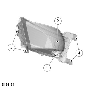
Halogen Headlamp
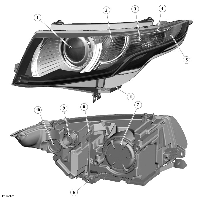
- Projector module - low/high beam headlamp
- Side lamp/Daytime Running Lamp (DRL) LED
- Turn signal indicator
- Side marker lamp LED (NAS only)
- Amber side reflector (NAS only)
- Headlamp mounting bracket
- Halogen bulb access cover
- Release lever
- Electrical connector
- Turn signal indicator bulb holder
The halogen headlamp uses a projector module which comprises an ellipsoidal lens with a solenoid controlled shutter to change the beam output from low to high beam.
The halogen headlamp is a self contained unit located within the headlamp assembly. The unit comprises a reflector, an adaptor ring, the lens, a shutter controller and the halogen bulb, which together forms an assembly known as the projector module. The reflector is curved and provides the mounting point for the xenon bulb.
The HB3 bulb is located in an integral holder which locates in a keyway to ensure the correct alignment in the reflector and is secured by rotating to the locked position. The shutter controller is a solenoid which operates the shutter mechanism via a lever. The shutter is used to change the beam projection from low beam to high beam and vice versa.
ADAPTIVE FRONT LIGHTING SYSTEM (AFS)
The AFS is controlled by a Headlamp Leveling Control Module (HLCM) which is located in the engine compartment, on the passenger side suspension turret panel. The HLCM is a dual function control module which can process and control the headlamp leveling and the AFS headlamp systems. The same module is used on vehicles without AFS but fitted with xenon headlamps.
The system operates by the HLCM receiving inputs from the ECM (engine control module) for engine running signal, the ABS (anti-lock brake system) control module for steering angle and vehicle speed and a reverse gear input from the transmission.
The HLCM processes these signals and provides an output to the headlamp leveling motors to adjust the headlamp horizontal aim according to vehicle speed and steering angle.
NOTE: In markets with Daytime Running Lamps (DRL), the AFS system will not operate when the DRL are active.
The HLCM is connected on the high speed CAN bus to receive information from other vehicle systems. The HLCM is connected to the AFS headlamps on a dedicated LIN bus. The HLCM calculates, using input data from other systems, the required position of the horizontal adjustment of the projector modules. The position information is then output on the LIN bus to the AFS Headlamps. The HLCM outputs the appropriate signals to drive the AFS stepper motors in the headlamp to the appropriate position.
The horizontal position of the projector modules is dependent on a number of input variables. The position is determined by vehicle speed and steering angle. When reverse gear is selected, the projector modules are moved to the straight ahead position to avoid glare to other road users.
The angles of each projector module differ to give the correct spread of light, for example, when turning left, the left hand projector module will have a greater swiveling angle than the right hand projector module.
AFS Operation
When the HLCM receives an ignition on signal, the control module performs the initialization procedure which ensures that the headlamps are correctly aligned on both their vertical and horizontal axes.
The AFS swivel initialization starts less than 1 second after the headlamp leveling initialization is activated to ensure that the headlamps are at or below the 0 degree position in the vertical axis, thus preventing glare to oncoming vehicles. The AFS swivel initialization is completed in less than 2.5 seconds. The left and right AFS actuator motors are powered from the 0 degree position to a small movement to the inboard position, then another small movement to the outboard position and then back to the 0 degree position.
Failure Mode
In the event of a failure of the AFS system, a warning indicator in the instrument cluster is illuminated to warn the driver.
The AFS warning indicator illuminates when the ignition is in power mode 6 (ignition on) and will flash continuously until the fault is rectified. The AFS warning indicator will also be illuminated if a failure of the steering angle sensor or the vehicle speed signal is detected.
Illumination of the AFS warning indicator does not necessarily mean that there is a fault with the AFS system. The fault may be caused by a failure of another system such as steering angle sensor or the vehicle speed signal missing, preventing the AFS system operating correctly.
The HLCM performs a diagnostic routine every time AFS is requested. If any fault is found, the HLCM will suspend the operation of the AFS function.
If the AFS leveling system has failed with the xenon projector module in a position other than the correct straight ahead position, the HLCM will attempt to drive the projector module to a position a small amount lower than the standard position. If the swivel function has failed, the HLCM will lower the projector module using the leveling actuator motors to a position much lower than standard to prevent excess glare to oncoming vehicles.
The HLCM software can detect an internal failure of the HLCM control circuits. The HLCM will power the projector modules to the zero position and prevent further operation.
Faults can be investigated by interrogating the HLCM using a Land Rover approved diagnostic tool to check for fault codes.
STATIC BENDING LAMPS (XENON ONLY)
NOTE: The static bending lamps are not fitted to NAS vehicles.
The LED static bending lamps are designed to illuminate the direction of travel when cornering at low speeds. The static bending lamp functionality, which is controlled by the CJB and the headlamp leveling control module, operates using inputs from the steering angle sensor and vehicle speed information from the ABS control module. The static bending lamp is incorporated into the headlamp assembly. The design of the lens projects a spread of light from the vehicle at approximately 45 degrees to the vehicle axis. The static bending lamp uses LEDs located in the headlamp housing The static bending lamps operate with a steering angle sensor CAN bus signal which is received by the CJB. The CJB monitors this signal and vehicle speed and activates the static bending lamp LED. When the operation parameters of the lamp are reached, the CJB fades the static bending lamp LED on using a PWM (pulse width modulation) voltage over a period of approximately 2 seconds. When the lamp is switched off, the CJB fades the LED off by decreasing the PWM voltage in a linear manner depending on steering angle and vehicle speed. The static bending lamps can only be active for a maximum of 3 minutes
NOTE: Static bending lamps only operate when the transmission is in DRIVE or in SPORT.
HEADLAMP LEVELING
Headlamp leveling provides for the adjustment of the vertical aim of the headlamps to minimize glare to other road users when the vehicle attitude changes due to vehicle loading.
Two types of headlamp leveling are available dependent on the type of headlamps fitted to the vehicle:
- Manual headlamp leveling - Halogen headlamps only
- Automatic headlamp leveling - Xenon headlamps only.
Manual Headlamp Leveling - Halogen Headlamps Only
NOTE: Headlamp leveling is not available on NAS vehicles with halogen headlamps.
The manual system comprises the following components:
- Two headlamp leveling motors
- Headlamp leveling rheostat rotary control.
A rotary thumbwheel controller is located adjacent to the instrument panel dimmer control in the auxiliary lighting switch.
The rotary thumbwheel controller is connected to a rheostat which gives a variable output to the headlamp leveling stepper motors. The motors respond to the output and move to adjust the headlamp vertical alignment as required.
In power mode 6 or above the motors in the lamps are driven from the extended ignition relay in the CJB, via a fuse to each lamp motor.
Movement of the leveling rotary control produces a variable voltage output (hardwire connection). The motors react to the supplied voltage and move the headlamp to the requested position which relates to the supplied voltage from the leveling rotary control. The headlamps can be lowered from their unladen position to compensate for changes in vehicle attitude due to loading.
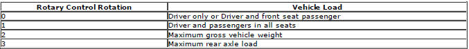
The control has four defined positions to compensate for a drop in height at the rear of the vehicle and avoid dazzle to oncoming drivers. The positions are defined as follows:
Automatic Headlamp Leveling - Xenon Headlamps Only
Automatic headlamp leveling is only available on vehicles with xenon headlamps. The system is not a Dynamic headlamp leveling system and changes in vehicle inclination due to positive and negative acceleration are not compensated.
Automatic headlamp leveling provides for the static, periodic adjustment of the vertical aim of the headlamps to minimize glare to other road users when the vehicle attitude changes due to loading.
Automatic headlamp leveling is controlled by a Headlamp Leveling Control Module (HLCM) which is located in the engine compartment, on the passenger side suspension turret panel. The HLCM is a dual function control module which can process and control the headlamp leveling and the AFS headlamp systems (if fitted).
The headlamp leveling system comprises the following components and information from other vehicle systems:
- Front and rear vehicle height sensors
- Two headlamp leveling, vertical adjustment motors
- HLCM
- Ignition in power mode 6 or above.
When the ignition is in power mode 6 or above, power is supplied, via the extended ignition relay in the CJB, to the lighting control switch, the headlamp leveling motors (or AFS motors if fitted) and to the HLCM.
When the lighting control switch is moved to the side lamp or headlamp position, a LIN bus message is passed from the clockspring to the CJB for the selected function. The CJB then issues a 'lights on' message on the high speed CAN bus to the HLCM.
The HLCM uses signals from the front and rear height sensors to periodically re-align the vertical aim of the headlamps to their optimum position.
DAYTIME RUNNING LAMPS (DRL)
DRL are a market requirement in certain countries.
For market information and DRL functionality refer to the DRL section.
Refer to: Daytime Running Lamps (DRL) (417-04 Daytime Running Lamps (DRL), Description and Operation).
Halogen Headlamps
The DRL use the LED side lamp. The DRL operate at a higher intensity than the side lamp illumination. The LED intensity is controlled by the CJB using a PWM output.
Xenon Headlamps
The DRL use the LED signature side lamp. The DRL operate at a higher intensity output than the side lamp illumination.
The LED intensity is controlled by the CJB using a PWM output.
FRONT FOG LAMP
- LED light source
- Lens
- Attachment holes
- Electrical connector
Front fog lamps are available as an option or standard fitment on vehicles fitted with xenon headlamps and headlamp powerwash.
Two front fog lamps are located in apertures in the front bumper. Each lamp is secured in the bumper with 3 Torx screws which are covered with a removable finisher. The fog lamp has an adjuster which is used to set the fog lamp to the correct alignment.
The fog lamp uses an LED light source.
The front fog lamps are controlled by the CJB. When the ignition is in ignition power mode 6 or above and the lighting control switch is in the side lamp or headlamp position or AUTO position (and Rain Light Sensor is requesting low beam), the fog lamp switch can be rotated to activate the front fog lamps. A front fog lamp warning indicator is illuminated in the instrument cluster when the front fog lamps are active.
Front Fog Lamp Functionality (NAS and Canadian Markets Only)
The front fog lamps operate as described previously but with the following differences which cover local laws governing lamp usage.
If the low beam headlamps and the front fog lamps are on at the same time, when the high beam headlamps are switched on, the front fog lamps will be automatically switched off. When the high beam headlamps are subsequently switched off, the front fog lamps will be switched on automatically.
NOTE: The front fog lamps will also be switched off if the high beam 'flash' function is operated.
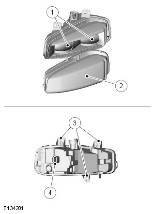
TAIL LAMP ASSEMBLY
- Side marker
- Turn signal indicator
- Reverse lamp
- Stop/Tail lamps
- Reverse lamp bulb
- Electrical connector
- Turn signal indicator bulb
The tail lamp assembly is a one piece unit which contains a stop/tail lamp, a turn signal indicator lamp and a reverse lamp.
The tail lamp assembly is located in a recess in the vehicle body. One stud on the outer edge of the lamp housing locates in a plastic clip on the vehicle body. The lamp is secured with two screws which are located on the inner edge of the lamp housing, near the tailgate aperture. In order to access the screws, removal of a small cover in the lamp housing is required.
Rear Stop/Tail Lamp
The upper lamp is a combined LED matrix for stop and tail lamp. The stop lamp is activated when the ignition is in ignition power mode 6 and the brake pedal switch is active (by depressing the brake pedal). The high mounted stop lamp will also be activated when the brake pedal is pressed. The stop lamps can also be activated by the ABS when Hill Descent Control (HDC) is active (if fitted). The ABS module sends a high speed CAN bus message to the CJB which supplies power to the stop lamps and high mounted stop lamp.
The side lamps are operated by selecting side lamps or headlamps on the lighting control switch. The side lamps can be switched on at all times and are not dependent on the ignition power mode 6. The side lamps will also be illuminated when the lighting control switch is in the AUTO position and a 'lights on' signal is received by the CJB from the rain/light sensor.
Turn Signal Indicator Lamp
The turn signal indicator lamp is located next to the stop/tail lamp and uses a Silvervision 24W bulb.
The turn signal indicator lamps are operated by the left steering column multifunction switch or by the hazard warning lamp switch. The left steering column multifunction switch is only active with the ignition in power mode 6, the hazard warning lamp switch is active at all times. When active, the turn signal indicator lamps will flash at a frequency cycle of 400ms on 400ms off.
If a bulb fails, the remaining turn signal indicator lamp bulb on that side of the vehicle flashes at normal speed. The applicable turn signal indicator in the instrument cluster will flash at double speed to alert the driver to the bulb failure.
Reverse Lamp
The reverse lamp is located adjacent to the turn signal indicator lamp and uses a 16W bayonet fitting bulb.
The reverse lamp is active when the ignition is in power mode 6 and the CJB receives a reverse selected signal on the high speed CAN bus. The automatic and manual transmissions have a reverse switch which senses when reverse is selected and sends the state out on CAN to the CJB.
Rear Fog Lamp
- Rear fog lamp bulb holder
- Rear fog lamp bulb
- Attachment holes
- Attachment
The rear fog lamp is located in the bumper and uses a 19W bayonet fitting bulb.
The rear fog lamp is controlled by CJB. When the ignition switch is in power mode 6 or greater and the lighting control switch is in the side lamp or headlamp position, the rear fog lamp switch on the left steering column multifunction switch can be operated to activate the rear fog lamps. A rear fog lamp warning indicator is illuminated in the instrument cluster when the rear fog lamps are active.
Side Marker Lamp
The side marker lamp is located in the outer part of the tail lamp assembly, adjacent to rear fog lamp and uses LED.
The side marker lamp is active at all times when the side lamps are selected on using the light control module. The side marker lamps will also be illuminated when the light control module rotary switch is in the 'AUTO' position and a 'lights on' signal is received by the CJB from the light sensor.
HAZARD WARNING LAMPS
The hazard warning lamps are controlled by a non-latching switch in the center of the instrument panel. The hazard warning lamps operate at all times when selected and are not dependent on the ignition power mode.
When the hazard warning lamps are selected on, all of the front, rear and side repeater turn signal indicator lamps operate as previously described and both left and right turn signal indicators in the instrument cluster also flash. The hazard warning lamps flash at a rate of 400ms on and 400ms off. When the hazard warning lamps are active, they override any request for turn signal lamp operation.
If a trailer is fitted, the trailer turn signal indicators will flash at the same frequency as the vehicle turn signal indicators.
The trailer warning indicator in the instrument cluster will also flash. If a trailer turn signal indicator bulb is defective, the trailer warning indicator will not flash.
The hazard warning lamps can also be activated by a crash signal from the RCM. This is received by the CJB which activates the hazard warning lamps. The hazard warning lamps can be cancelled when crash mode is cancelled by the RCM.
LICENSE PLATE LAMPS
Two license plate lamps are fitted in the tailgate handle, above the license plate in the upper tailgate. Each lamp uses LEDs.
The lamps are secured in the upper tailgate handle with integral clips. The lamps can be released from the handle using a small, flat blade screwdriver. The license plate lamps are active at all times when the side lamps or headlamps are switched on.
HIGH MOUNTED STOP LAMP
The high mounted stop lamp is located in the tailgate. Access to the lamp is by removal of the upper tailgate interior trim panel. After releasing the lamp retaining clips, the lamp can be removed from outside the vehicle.
The lamp comprises a plastic housing with a red colored lens. The lamp is illuminated by LEDs.
The high mounted stop lamp is activated, along with the tail lamp stop lamps, when the ignition is in power mode 6 or above and the brake pedal switch is active (by pressing the brake pedal).
The high mounted stop lamp and the stop lamps can also be activated by the ABS when Hill Descent Control (HDC) is active (if fitted). A signal on the high speed CAN bus from the ABS module is passed to the CJB which supplies power to the stop lamps.
SIDE REPEATER LAMPS
The side repeater lamps are located in the external rear view mirrors.
The side repeater lamps use LEDs. The side repeater lamps have the same functionality as the front and rear turn signal indicator lamps and are operated by the left steering column multifunction switch or by the hazard warning lamp switch.
The steering column multifunction switch is only active with the ignition in power mode 6, the hazard warning lamp switch is active at all times, regardless of the power mode. When active, the side repeater lamps will flash at a frequency cycle of 400ms on and 400ms off. If a side repeater lamp fails, the turn signal indicator lamps continue to flash at the normal rate.
TRAILER LIGHTING
Several different types of trailer socket can be fitted to the vehicle depending on market specifications. Refer to the Electrical Reference Library for specific socket details.
The CJB monitors the turn signal indicator lamps and can detect if more than two lamps are fitted (the side repeater lamps are not monitored). When a trailer is detected, the trailer warning indicator in the instrument cluster will flash in synchronization with the turn signal indicators.
If one or more of the turn signal indicator lamps on the vehicle or the trailer are defective, the trailer warning indicator will not flash to alert the driver to the bulb failure.
INSTRUMENT PANEL DIMMER CONTROL
The dimmer rotary thumbwheel controller is located adjacent to the headlamp leveling control (when fitted) in the auxiliary lighting switch. The dimmer control provides a PWM output to control the illumination brightness of the instrument cluster, switches and other instrument panel illumination.
The dimmer rotary thumbwheel is connected to a rheostat and a high side switch. The rheostat is a variable resistor which provides a high or low resistance according to its set position. This output is passed to a switchable capacitor or a high side switch. The high side switch uses the output from the rheostat to determine the switching frequency of the capacitor which provides the PWM output of between 8 and 12V to determine the brightness of the illumination.
HEADLAMP DELAY
The CJB controls a headlamp delay function which illuminates the driveway after leaving the vehicle. The headlamp delay will operate on low beam headlamps only when the lighting control switch is in the AUTO position and the ignition is off (power mode 0) or in accessory power mode 4.
The headlamp delay is activated when the lighting control switch is in the AUTO position and the engine is switched off.
The message center displays a 'HEADLIGHT DELAY' message and the low beam headlamps will be activated for a period of approximately 30, 60 or 120 seconds. After the delay period, the CJB automatically switches off the delay function, extinguishing the headlamps. The delay period can be adjusted using the instrument cluster 'Vehicle Settings' menu. The feature can also be disabled using this menu.
The headlamp delay feature can also be switched on when approaching the vehicle or switched off by pressing the headlamp button on the smart key.
DIAGNOSTICS
The diagnostic socket is located in the lower instrument panel closing panel, on the driver side, below the steering column.
Various lighting system functions are monitored by different systems which can store fault information. This can be retrieved using a Land Rover approved diagnostic system.
Exterior Lighting
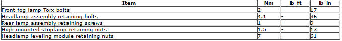
Torque Specifications
READ NEXT:
 Headlamp Adjustment
NOTE: The headlamp setting is 1.2 % below horizontal and parallel.
1. Align the headlamp beam setting equipment to one headlamp.
2. Switch the headlamps on and to dipped beam.
3. NOTE: NAS vehicles ha
Headlamp Assembly
Removal
NOTE: Removal steps in this procedure may contain installation details.
1. WARNING: Make sure to support the vehicle with axle stands.
Raise and support the vehicle.
2.
3.
4. NOTE: Some com
Headlamps
Principle of Operation
Three types of headlamp are available: Halogen, bi-xenon or Adaptive Front
Lighting System (AFS).
For a detailed description of the headlamps operation, refer to the relevant
SEE MORE:
Important information
The information contained in this handbook covers all vehicle derivatives and
optional equipment,
some of which may not be fitted to your vehicle. Due to printing cycles, this
handbook may include
descriptions of options before they become generally available.
The vehicle options, hardware an
Symbols used in this handbook
Safety warnings indicate either a procedure which must be followed
precisely, or
information that should be considered with great care, in order to avoid the
possibility
of personal injury.
Cautions indicate either a procedure which must be followed precisely, or
information that
should
