Range Rover Evoque: Control Diagram, System Operation
Control Diagram
NOTE: A = Hardwired; D = High speed CAN (controller area network) bus; O = LIN (local interconnect network) bus
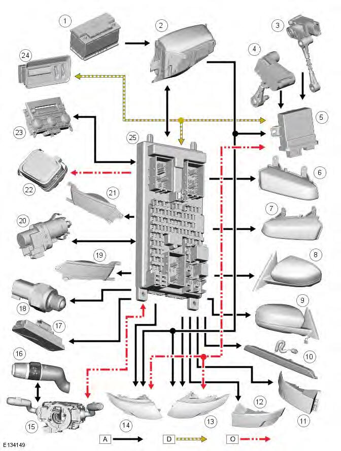
- Battery
- BJB (battery junction box)
- Front height sensor
- Rear height sensor
- Headlamp leveling control module
- Front right fog lamp
- Front left fog lamp
- Left side repeater lamp
- Right side repeater lamp
- High mounted stop lamp
- Left tail lamp assembly
- Right tail lamp assembly
- Left headlamp assembly
- Right headlamp assembly
- Clockspring
- Left steering column multifunction switch
- License plate lamp
- Reverse lamp switch
- Left rear fog lamp
- Brake pedal switch
- Right rear fog lamp
- Rain/light sensor
- Hazard warning lamp switch
- Auxiliary lighting switch
System Operation
CJB (central junction box)
The CJB receives exterior lighting related inputs from the following switches:
- Left steering column multifunction switch
- Side lamp position
- Headlamp position
- Automatic (AUTO) position (if fitted)
- Front fog lamp switch (if fitted)
- Rear fog lamp switch
- Turn signal indicators and high beam/headlamp flash
- Brake switch
- Headlamp leveling control (halogen only)
- Hazard warning lamp switch
- Rain/light sensor (LIN signal).
Circuit Protection
Two 60 Amp fusible links in the BJB protect the power feed to the CJB, left and right lighting circuits respectively. All exterior lighting circuits are protected by Field Effect Transistors (FETs), located in the CJB, which can detect overloads and short circuits.
The FETs respond to heat generated by increased current flow caused by a short circuit. On a normal circuit this would cause the fuse to blow. The FETs respond to the heat increase and disconnect the supply to the affected circuit. When the fault is rectified or the FET has cooled, the FET will reset and operate the circuit normally. If the fault persists the FET will cycle, disconnecting and reconnecting the power supply. The CJB stores fault codes which can be retrieved using a Land Rover approved diagnostic system. The fault code will identify that there is a fault on a particular output which assist in fault detection.
Alarm Indications
The exterior lighting system is used for alarm and disarm requests. When the driver locks or unlocks the vehicle, a visual indication of a successful lock or unlock request is displayed to the driver by the hazard flashers operating a number of times.
Refer to: Anti-Theft - Active (419-01A Anti-Theft - Active, Description and Operation).
Lights-On Warning Chime
When the ignition is in the off (power mode 0) or auxiliary (power mode 4) mode and the left steering column multifunction switch is in the side lamp or headlamp position, a warning chime will sound if the driver door is opened. This indicates to the driver that the exterior lights have been left on. The chime is generated from the instrument cluster sounder on receipt of a lights-on signal, a door open signal and an ignition off signal from the CJB on the high speed CAN bus.
Crash Signal Activation
When a crash signal is transmitted from the RCM (restraints control module), the CJB activates the hazard warning lamps and the turn signal indicator warning lamp in the instrument cluster. The hazard warning lamps will continue to operate until the ignition mode is changed to the auxiliary power mode 4, or the off power mode 0 or the RCM no longer transmits the crash signal.
Headlamp Delay Timer
The CJB controls a headlamp delay timer function which allows the headlamps to remain on for a period of time after leaving the vehicle. This is a driver convenience feature which illuminates the driveway after leaving the vehicle.
The timer is set within the instrument cluster 'Vehicle Set-up Menu'. The default timing is 30s, but the timing can be changed to between 0s (OFF), 30s (default), 60s, 120s and 240s.
Refer to: Information and Message Center (413-08 Information and Message Center, Description and Operation).
READ NEXT:
 Component Description
LEFT STEERING COLUMN MULTIFUNCTION SWITCH
Off position
Side lamps position
Headlamps position
AUTO - Automatic headlamps position (if fitted)
Front fog lamps switch
Rear fog lamps switch
High
Headlamp Adjustment
NOTE: The headlamp setting is 1.2 % below horizontal and parallel.
1. Align the headlamp beam setting equipment to one headlamp.
2. Switch the headlamps on and to dipped beam.
3. NOTE: NAS vehicles ha
Headlamp Assembly
Removal
NOTE: Removal steps in this procedure may contain installation details.
1. WARNING: Make sure to support the vehicle with axle stands.
Raise and support the vehicle.
2.
3.
4. NOTE: Some com
SEE MORE:
Mirror dip when reversing
If the vehicle is equipped with memory seats,
when reverse gear is selected the door mirrors
can be set to automatically adjust, providing an
improved viewing angle of the curb side for
reversing. The Reverse-dip mirror feature
must be switched on. See 56, VEHICLE
INFORMATION AND SETTINGS MENU
Interior mirror
Auto dimming mirror
1. Ambient light sensor.
2. High beam assist sensor.
Interior mirror dimming will adjust
automatically according to the amount of
ambient light when the ignition is on. If reverse
gear is selected, the automatic dimming
feature is turned off to allow maximum
visibility
