Range Rover Evoque: Electronic Engine Controls
Principles of Operation
For a detailed description of the 2.0L GTDi petrol electronic engine controls, refer to the relevant Description and Operation section in the workshop manual. REFER to: (303-14B Electronic Engine Controls - GTDi 2.0L Petrol)
Inspection and Verification
CAUTION: Diagnosis by substitution from a donor vehicle is NOT acceptable. Substitution of control modules does not guarantee confirmation of a fault, and may also cause additional faults in the vehicle being tested and/or the donor vehicle.
1. Verify the customer concern
2. Visually inspect for obvious signs of mechanical or electrical damage
Visual Inspection
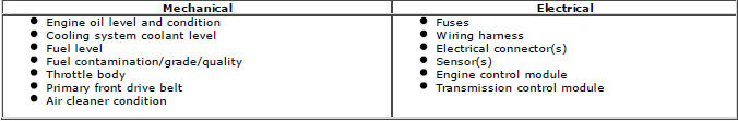
3. If an obvious cause for an observed or reported concern is found, correct the cause (if possible) before proceeding to the next step
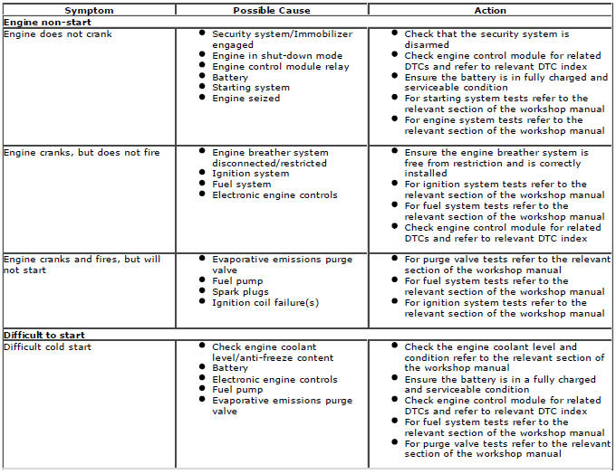
4. If the cause is not visually evident, verify the customer concern and refer to the Symptom Chart below, alternatively, check for Diagnostic Trouble Codes (DTCs) and refer to the DTC index
5. Check DDW for open campaigns. Refer to the corresponding bulletins and SSM's which may be valid for the specific customer complaint and carry out the recommendations as required
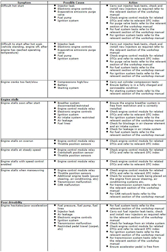
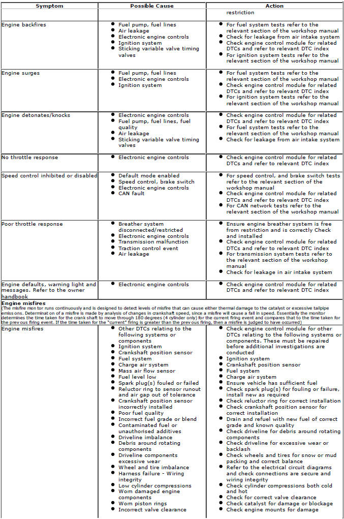
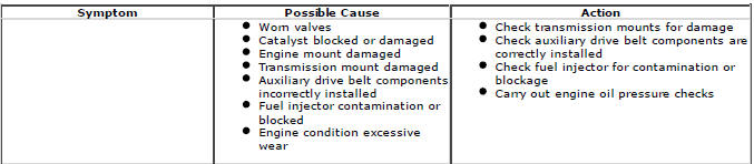
Symptom Chart
WARNINGS:
Wait at least 30 seconds after the engine stops before commencing any repair to the high-pressure fuel injection system. Failure to follow this instruction may result in personal injury
Place the vehicle in a well ventilated, quarantined, area and arrange "Fuel Fumes" signs about the vehicle
Before any work is carried out on the fuel system, ground the vehicle to earth and maintain the ground connection until the work is complete
Do not carry out any repairs to the fuel injection system with the engine running. The fuel pressure within the system can be considerably high. Failure to follow this instruction may result in personal injury.
Do not smoke or carry lighted tobacco or open flame of any type when working on or near any fuel related components. Highly flammable vapours are always present and may ignite. Failure to follow these instructions may result in personal injury
After carrying out repairs, the fuel system must be checked visually for leaks. Failure to follow these instructions may result in personal injury
If taken internally do not induce vomiting, seek immediate medical attention. Failure to follow these instructions may result in personal injury
If fuel contacts the eyes, flush the eyes with cold water or eyewash solution and seek medical attention.
Wash hands thoroughly after handling fuel, as prolonged contact may cause irritation. Should irritation develop, seek medical attention
This procedure involves fuel handling. Be prepared for fuel spillage at all times and always observe fuel handling precautions. Failure to follow these instructions may result in personal injury.
CAUTION: Always carry out the cleaning process before carrying out any repairs to the fuel injection system components. Failure to follow these instructions may result in foreign matter ingress to the fuel injection system
NOTES:
If the control module or a component is suspect and the vehicle remains under manufacturer warranty, refer to the warranty policy and procedures manual (section B1.2), or determine if any prior approval programme is in operation, prior to the installation of a new module/component
Generic scan tools may not read the codes listed, or may read only 5-digit codes. Match the 5 digits from the scan tool to the first 5 digits of the 7-digit code listed to identify the fault (the last 2 digits give extra information read by the manufacturer-approved diagnostic system)
When performing voltage or resistance tests, always use a digital multimeter accurate to three decimal places and with a current calibration certificate. When testing resistance, always take the resistance of the digital multimeter leads into account
Check and rectify basic faults before beginning diagnostic routines involving pinpoint tests
Inspect connectors for signs of water ingress, and pins for damage and/or corrosion
If diagnostic trouble codes are recorded and, after performing the pinpoint tests, a fault is not present, an intermittent concern may be the cause. Always check for loose connections and corroded terminals
DTC index
For a complete list of all diagnostic trouble codes that could be logged on this vehicle.
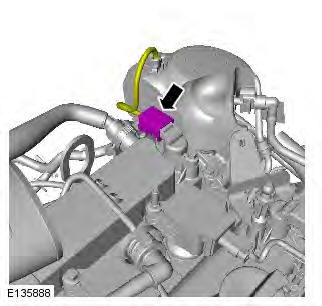
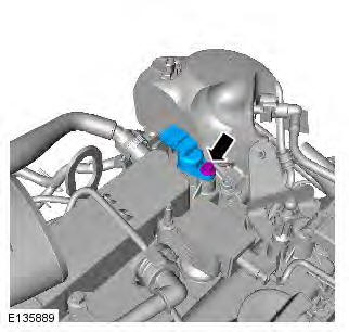
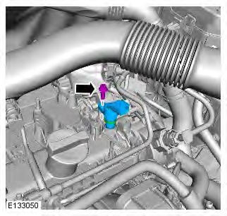
Exhaust Camshaft Position (CMP) Sensor
Removal
1. Refer to: Engine Cover - GTDi 2.0L Petrol (501-05 Interior Trim and Ornamentation, Removal and Installation).
2. Refer to: Air Cleaner Intake Pipe (303-12B Intake Air Distribution and Filtering - GTDi 2.0L Petrol, Removal and Installation).
3.
4. CAUTIONS:
Lubricate the O-ring seals.
The O-ring seals are to be reused unless damaged.
Take care not to damage the O-ring seals during installation.
NOTE: If the O-ring is damaged, the sensor must be replaced.
Torque: 6 Nm
Installation
1. To install, reverse the removal procedure.
Intake Camshaft Position (CMP) Sensor
Removal
NOTE: Removal steps in this procedure may contain installation details.
1. Refer to: Engine Cover - GTDi 2.0L Petrol (501-05 Interior Trim and Ornamentation, Removal and Installation).
2.
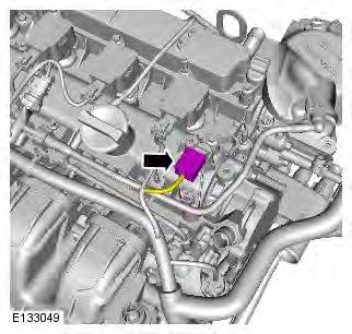
3. CAUTION: Lubricate the O-ring seal. Torque: 7 Nm
Installation
1. To install, reverse the removal procedure.
READ NEXT:
 Transmission Description - Component Location
Component Location
COMPONENT LOCATION
Auxiliary battery module
Transmission Control Switch (TCS)
Upshift (+) paddle switch
Downshift (-) paddle switch
Transmission and Gear Shift Module (GSM) b
SEE MORE:
Charging or replacing the vehicle battery
If the vehicle battery should require charging,
the battery must be removed from the vehicle.
Consult your Dealer/Authorised Repairer.
Battery disconnection,
removal and
replacement should be carried out only
by qualified personnel. Consult your
Dealer/Authorised Repairer.
Used batteries
Fuse box locations
Fuse box locations
When a fuse box lid is
removed, take
care to protect the box from moisture,
and refit the lid at the earliest
opportunity.
Engine compartment - fuse box access:
1. Remove the two plastic fixings.
2. Pull the tube up to release from the air box.
3. Delatch the tabs. Th
