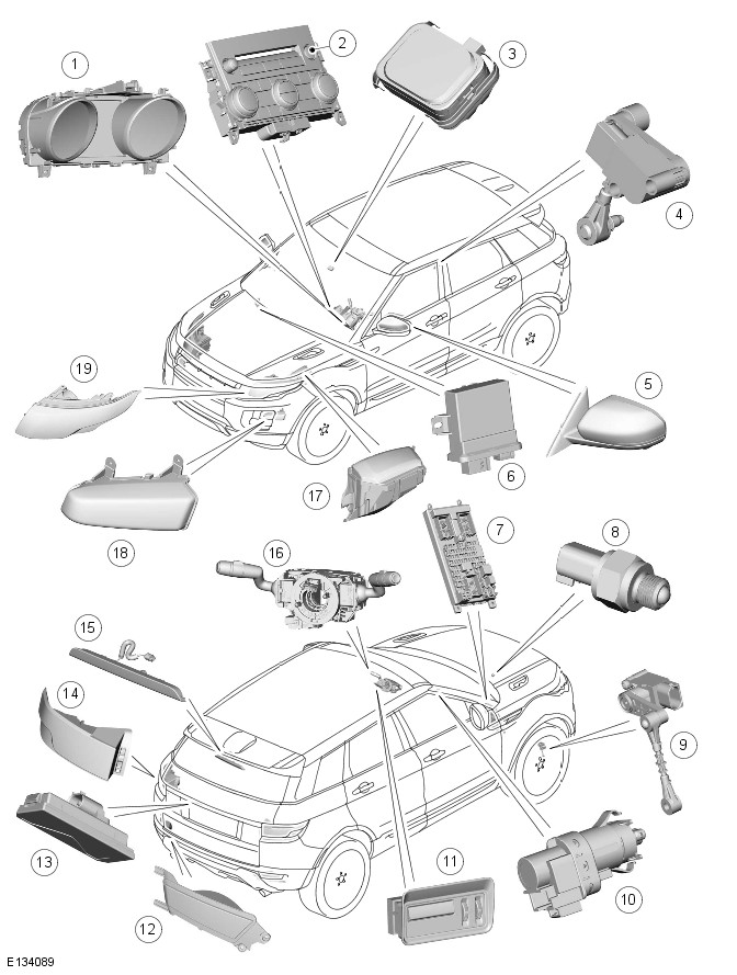
Range Rover Evoque: Exterior Lighting - Component Location
COMPONENT LOCATION

- Instrument cluster
- Hazard flasher switch
- Rain/Light sensor
- Rear height sensor (Xenon headlamps only)
- Side turn signal indicator lamp
- Headlamp leveling control module
- CJB (central junction box)
- Reverse lamp switch
- Front height sensor (Xenon headlamps only)
- Stop lamp switch
- Auxiliary lighting switch
- Rear fog lamp
- Number plate lamp
- Tail lamp unit
- High mounted stop lamp
- LH (left-hand) steering column multifunction switch
- BJB (battery junction box)
- Front fog lamp
- Headlamp
Exterior Lighting - Overview
OVERVIEW
The lighting systems are controlled by the BJB (battery junction box) and the CJB (central junction box). The junction boxes contain fuses, relays and microprocessors to control the power supply and functionality of the lighting systems.
Driver lighting selections using the left steering column multifunction switch are passed to the CJB via the clockspring on a LIN (local interconnect network) bus. The auxiliary lighting switch is hardwired directly to the CJB and is only used for manual headlamp leveling on vehicles with halogen headlamps. The CJB provides circuit protection for all exterior lighting circuits.
The lighting system has an 'auto' lights function which is controlled by the CJB on receipt of signals from the rain/light sensor located at the top of the windscreen. The exterior lights are turned on or off in response to ambient light signals from the rain/light sensor on a LIN bus connection to the CJB . The auto lights can also be activated when the windshield wipers are activated by signals from the rain sensor, which is located at the top of the windshield or when the driver activates the wipers in the fast wipe position.
Three levels of headlamp specification are available; halogen, xenon or xenon with Adaptive Front lighting System (AFS).
In certain markets the headlamps feature a static bending lamp which illuminates the area at the side of the vehicle when turning into driveways for example. North American Specification (NAS) vehicles have a side lamp/DRL (daytime running lamps) installed in the headlamp assembly in place of the cornering/static bending lamp. Only the D3S xenon bulb and the xenon ballast resistor are serviceable, no other headlamp components are available individually. Failure of any LED (light emitting diode) requires replacement of the complete lamp assembly.
The tail lamps comprise a single lamp assembly on each side of the vehicle. The turn signal indicator, side and stop lamps, side marker lamps and reverse lamps are located in each tail lamp assembly. Rear fog lamps are mounted in the rear bumper. The rear lamp assemblies require removal for bulb replacement.
All versions of the headlamps have impact resistant polycarbonate lenses. Removable covers at the rear of the headlamps allow for bulb replacement. The headlamps require removal for bulb replacement.
The headlamps use a projector unit. The xenon headlamps use a D3S xenon bulb which operates in both low and high beam. Halogen projector headlamps use a HB3 halogen bulb which also operates in both low and high beam.
Headlamp powerwash is a standard fitment on xenon headlamps.
Static dynamic leveling is standard on all xenon headlamps. The static dynamic system uses height sensors fitted to the front and rear suspension and a Headlamp leveling Control Module (HLCM) which periodically monitors the vehicle attitude and adjusts the headlamp vertical alignment accordingly.
Manual headlamp leveling is used only on vehicles fitted with halogen projector lamps. A rotary leveling thumbwheel is located in the auxiliary lighting switch in the instrument panel, adjacent to the steering column.
Turn signal indicators and high and low beam functions are controlled from the left steering column multifunction switch.
The turn signal indicators have a lane change feature. A single press and release of the multifunction switch in either direction will operate the selected turn signal indicators for 3 cycles.
An Auto High Beam (AHB) system can also be fitted which automatically controls the high beam headlamps.
Exterior Bulb Type/Rating
The following table shows the bulbs used for the exterior lighting system and their type and specification.


