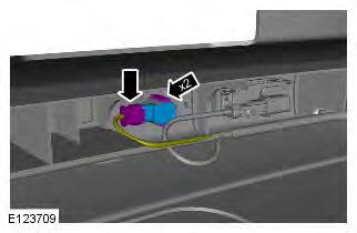
Range Rover Evoque: Front Inner Parking Aid Sensor
Removal
CAUTION: LH illustration shown, RH is similar.
NOTES: Removal steps in this procedure may contain installation details.
The ignition must be switched off.
1. WARNING: Make sure to support the vehicle with axle stands. Raise and support the vehicle.
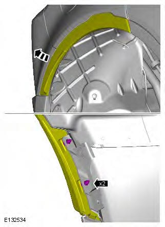
2. Refer to: Front Bumper Cover (501-19 Bumpers, Removal and Installation).
3. NOTE: Some variation in the illustrations may occur, but the essential information is always correct.
Installation
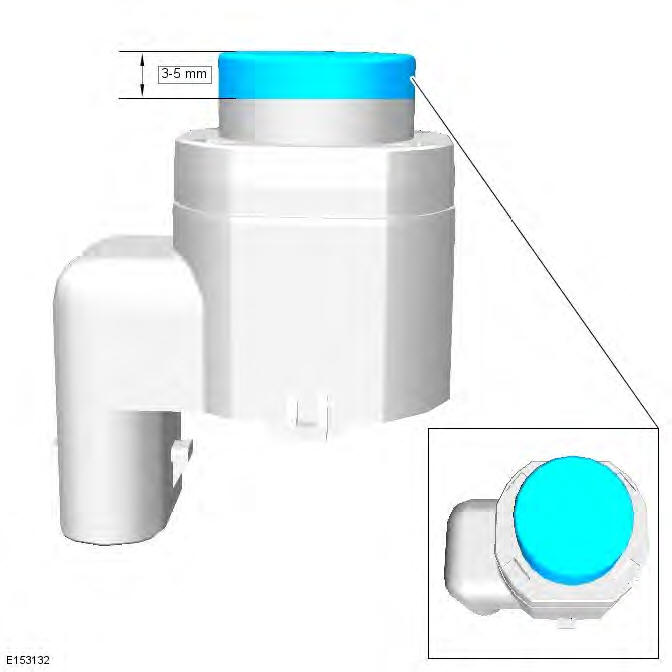
1. CAUTION: If a new sensor is installed, make sure that the area illustrated is the only area painted. Failure to follow this instruction may result in the component malfunctioning.
NOTE: On vehicles that are equipped with black or unpainted bumpers, the sensor(s) do not require painting.

2. To install, reverse the removal procedure.
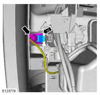
Front Outer Parking Aid Sensor
Removal
CAUTION: LH illustration shown, RH is similar.
NOTES: Removal steps in this procedure may contain installation details.
The ignition must be switched off.
1. WARNING: Make sure to support the vehicle with axle stands. Raise and support the vehicle.
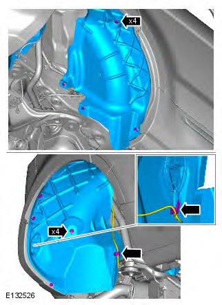
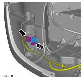
2. Refer to: Fender Splash Shield (501-02 Front End Body Panels, Removal and Installation).
3. NOTE: Some variation in the illustrations may occur, but the essential information is always correct.
Installation
1. CAUTION: If a new sensor is installed, make sure that the area illustrated is the only area painted. Failure to follow this instruction may result in the component malfunctioning.
NOTE: On vehicles that are equipped with black or unpainted bumpers, the sensor(s) do not require painting.

2. To install, reverse the removal procedure.
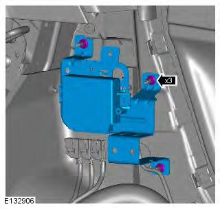
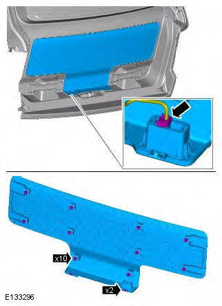
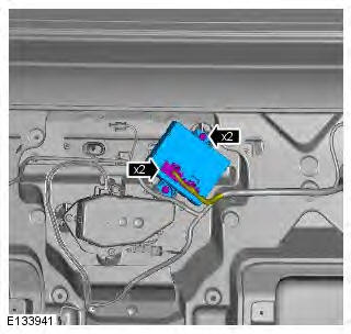
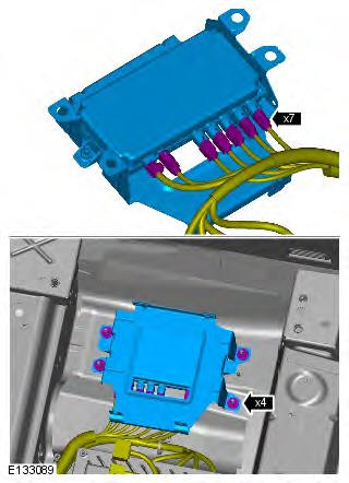
Parking Aid Module
Removal
NOTES: If a new parking aid module is to be installed, configure the parking aid module using the Land Rover approved diagnostic system.
Removal steps in this procedure may contain installation details.
The ignition must be switched off.
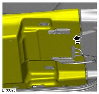
1. Refer to: Loadspace Trim Panel (501-05 Interior Trim and Ornamentation, Removal and Installation).
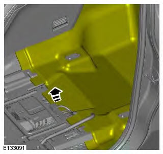
2.
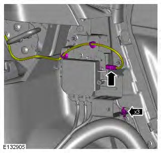
3. Torque: 10 Nm
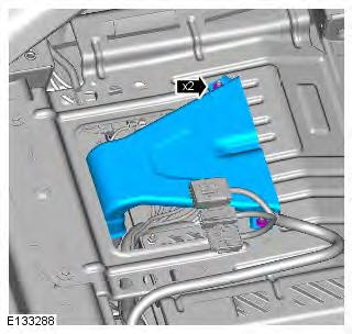
4. Torque: 20 Nm
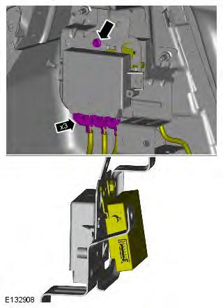
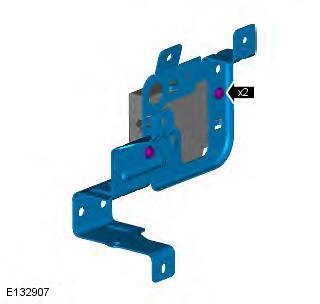
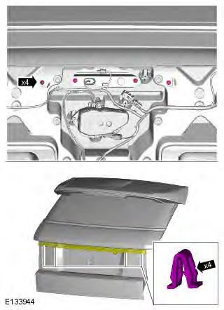
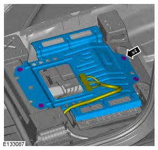
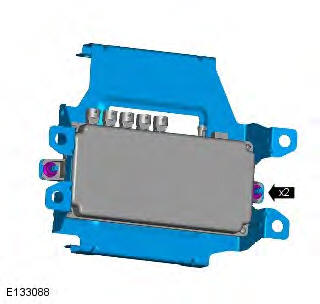
5. NOTE: Do not disassemble further if the component is removed for access only.
Torque: 10 Nm
Installation
1. To install, reverse the removal procedure.
Rear Inner Parking Aid Sensor
Removal
NOTES:
Removal steps in this procedure may contain installation details.
The ignition must be switched off.
1. WARNING: Make sure to support the vehicle with axle stands. Raise and support the vehicle.
2. Refer to: Rear Bumper Cover (501-19 Bumpers, Removal and Installation).
3. NOTE: RH illustration shown, LH is similar.
Installation
1. CAUTION: If a new sensor is installed, make sure that the area illustrated is the only area painted. Failure to follow this instruction may result in the component malfunctioning.
NOTE: On vehicles that are equipped with black or unpainted bumpers, the sensor(s) do not require painting.

2. To install, reverse the removal procedure.
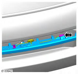
Rear Outer Parking Aid Sensor
Removal
NOTES:
Removal steps in this procedure may contain installation details.
The ignition must be switched off.
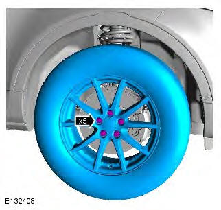
1. WARNING: Make sure to support the vehicle with axle stands. Raise and support the vehicle.
2. Torque: 133 Nm
3. CAUTION: Take extra care not to damage the component.
NOTE: The step must be carried out on both sides.
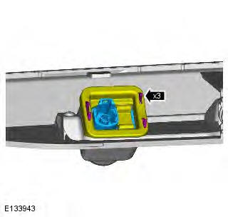
4.
5. NOTE: RH illustration shown, LH is similar.
Installation
1. CAUTION: If a new sensor is installed, make sure that the area illustrated is the only area painted. Failure to follow this instruction may result in the component malfunctioning.
NOTE: On vehicles that are equipped with black or unpainted bumpers, the sensor(s) do not require painting.
2. To install, reverse the removal procedure.
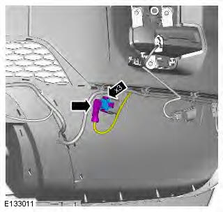
Front Parking Aid Camera
Removal
NOTES: Removal steps in this procedure may contain installation details.
The ignition must be switched off.
1. WARNING: Make sure to support the vehicle with axle stands. Raise and support the vehicle.
2. Refer to: Front Bumper Cover (501-19 Bumpers, Removal and Installation).
3. CAUTIONS:
Make sure that the component is correctly located on the locating dowels.
Take extra care not to damage the wiring harnesses.
NOTE: RH illustration shown, LH is similar.
Installation
1. To install, reverse the removal procedure.
2. If a new component has been installed, configure using Land Rover approved diagnostic equipment.
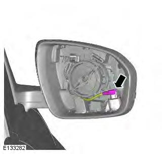
Side Parking Aid Camera
Removal
NOTES:
Removal steps in this procedure may contain installation details.
The ignition must be switched off.
1. Refer to: Exterior Mirror Glass (501-09 Rear View Mirrors, Removal and Installation).
2. CAUTION: Take extra care not to damage the wiring harnesses.
NOTE: RH illustration shown, LH is similar.
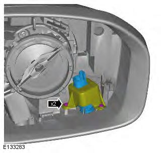
3. CAUTION: Take extra care not to damage the component.
NOTE: RH illustration shown, LH is similar.
Torque: 0.5 Nm
Installation
1. To install, reverse the removal procedure.
2. If a new component has been installed, configure using Land Rover approved diagnostic equipment.
Parking Aid Camera
Removal
NOTES:
Removal steps in this procedure may contain installation details.
The ignition must be switched off.
1.
2. Torque: 4 Nm
3. Torque: 4 Nm
4.
5. CAUTION: Make sure that the component is correctly located on the locating dowels.
Installation
1. To install, reverse the removal procedure.
2. If a new component has been installed, configure using Land Rover approved diagnostic equipment.
Parking Aid Camera Module
Removal
NOTES: Removal steps in this procedure may contain installation details.
The ignition must be switched off.
1. Refer to: Front Seat (501-10 Seating, Removal and Installation).
2.
3.
4. Torque: 10 Nm
5. Torque: 20 Nm
6. Torque: 10 Nm
7. NOTE: Do not disassemble further if the component is removed for access only.
Torque: 10 Nm
Installation
1. To install, reverse the removal procedure.
2. If a new component has been installed, configure using Land Rover approved diagnostic equipment.
Parking Aid
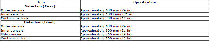
General Specification
Principles of Operation
For a detailed description of the parking aid system, characteristics and limitations refer to the relevant description and operation section in the workshop manual. REFER to: (413-13 Parking Aid)
Parking Aid System On-Board Self-Test
As part of the strategy of the system if any DTCs are detected, a long high-pitched tone approx 3 seconds will sound and the parking aid switch (where fitted) indicator LED will flash 6 times at ignition on
- If a fault is present when the parking aid system is activated then the parking aid switch (where fitted) status LED will flash 6 times indicating an issue with front or rear parking aid sensors, wiring switch, parking aid control module or hard wired sounders
- The rear parking aid sounder/rear audio system will emit an error tone for approx 3 seconds at ignition on if a fault is detected with the front or rear sensors, the switch, or if there is a controller area network (CAN) bus error (Only applicable to vehicles fitted with front parking aid and a hard wired rear parking aid sounder). If there is a fault with the rear parking aid sounder the error tone will come from the front parking aid sounder unit (integral with the instrument cluster)
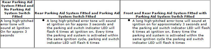
Audible and Visual Warnings when Parking Aid System is in Error State
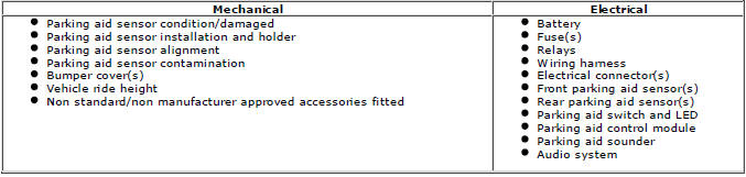
Inspection and Verification
CAUTIONS: If the control module or a component is suspect and the vehicle remains under manufacturer warranty, refer to the warranty policy and procedures manual (section B1.2), or determine if any prior approval programme is in operation, prior to the installation of a new module/component.
Diagnosis by substitution from a donor vehicle is NOT acceptable. Substitution of control modules does not guarantee confirmation of a fault, and may also cause additional faults in the vehicle being tested and/or the donor vehicle Do not apply any grease based products to any parking aid system connector or pins NOTE: Check DDW for open campaigns. Refer to the corresponding bulletins and SSMs which may be valid for the specific customer complaint and carry out the recommendations as required.
1. Verify the customer concern
2. Visually inspect for obvious signs of mechanical or electrical damage
3. Ensure that the parking aid sensor face is clear of contamination that could affect the performance of the sensor
Visual Inspection
4. If an obvious cause for an observed or reported concern is found, correct the cause (if possible) before proceeding to the next step
5. If the cause is not visually evident, check for diagnostic trouble codes (DTCs) and refer to the DTC index
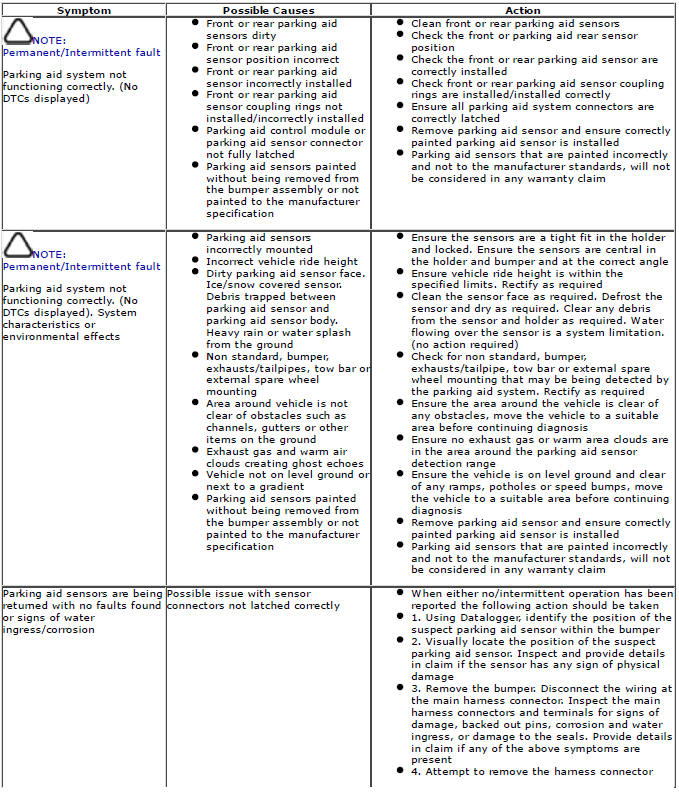
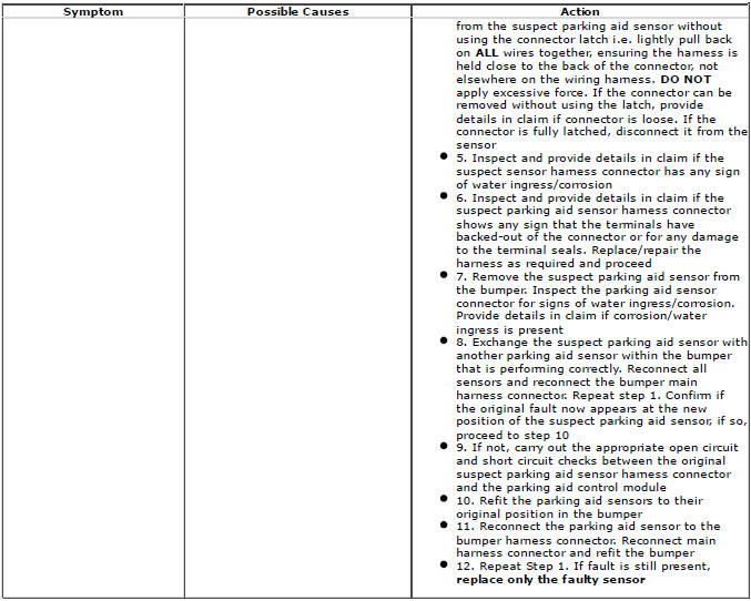
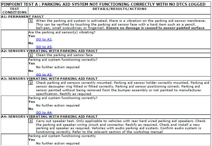
Symptom Chart
CAUTION: Do not apply any grease based products to any parking aid system connector or pins
NOTES:
Please note if this diagnosis is being carried out on a vehicle without a hard wired parking aid speaker, ensure the in car infotainment system is fully functional and configured correctly Parking aid sensors that are painted incorrectly and not to the manufacturer standards, will not be considered in any warranty claim
DTC Index
For a list of diagnostic trouble codes that could be logged on this vehicle, please refer to Section 100-00.
READ NEXT:
 Battery and Charging System - General Information
Battery Care
Requirements
1. INTRODUCTION
This document sets out the requirements for care and maintenance of batteries
and thereby the standard of battery care
at dealers and retailers for new vehic
SEE MORE:
Heating and ventilation controls
Controls
1. Temperature controls. For individual
driver/passenger settings.
2. Maximum defrost program.
3. Air distribution.
Note: More than one setting may be
selected at a time to achieve the desired
distribution.
4. AUTO mode. For fully automatic operation.
5. Heated windscreen.
6. He
Recirculation with pollution and humidity sensing
- Press the AUTO button briefly to activate
timed recirculation. The AUTO LED will
illuminate. The system automatically
selects fresh and recirculated air
dependent on pollution and cabin
humidity.
- Press and hold the AUTO button to activate
latched recirculation. The AUTO LED will
flash an
