Range Rover Evoque: Battery and Charging System - General Information
Battery Care Requirements
1. INTRODUCTION
This document sets out the requirements for care and maintenance of batteries and thereby the standard of battery care at dealers and retailers for new vehicles This applies to all types of 12 Volt Lead Acid Batteries used in Jaguar and Land Rover vehicles whether they are conventional flooded technology or Absorbed Glass Mat (AGM - also known as Valve Regulated Lead Acid (VRLA) ) technology and also applies to both Primary and Auxiliary Batteries. AGM batteries offer improved resistance to cycling as seen in stop start applications.
In order to prevent damage to the battery and ensure a satisfactory service life, all processes detailed within this document must be rigorously adhered to.
It is equally important therefore to note the following key points:
- All new vehicles leave the factory with either a transit relay installed and/or have a transit mode programmed into the vehicle control modules. The transit relay must be removed and the transit mode disabled (where applicable) using an approved diagnostic system, NOT MORE THAN 72 HOURS before the customer takes delivery.
- The battery can be discharged by the following mechanisms:
- Self Discharge: -A lead acid battery will very slowly discharge itself due to its own internal chemical processes whether it is connected to a vehicle or not.
- Quiescent Discharge: - The vehicle electrical systems when connected to the battery will draw charge from the battery.
12 Volt Lead Acid Batteries rely on internal chemical processes to create a voltage and deliver current. These processes and the internal chemical structure of the battery can be damaged if the battery is allowed to discharge over a number of weeks / months, or is left in a discharged state for a lengthy time period.
- On vehicles with conventional ignition keys, these must not be left in the ignition lock barrel when the transit relay has been removed, otherwise quiescent current will increase and the battery will discharge more rapidly.
- For keyless vehicles, the Smart Key must be stored at least 5m away from the vehicle when the vehicle is parked or stored.
- AGM Batteries are fully sealed and cannot have the electrolyte level topped up.
NOTE: Dealers and retailers involved in the storage / handling of vehicles and replacement batteries have a responsibility to ensure that only a fully charged battery may be processed through the distribution selling chain.
2. GENERAL RULES FOR BATTERY CARE
2.1 Dealer Demonstration Vehicles
Vehicles used as dealer demonstrator(s), in a showroom, must be connected to a showroom conditioner capable of delivering 50 Amps. This will prevent the battery from being damaged.
2.2 Software Reflash, SDD work or Ignition On related workshop activities
Due to the high electrical current demand and high depth of Discharge that can occur during vehicle software re-flash activities, SDD work or ignition on related work in the workshop, vehicles that are undergoing such activities MUST have a power supply capable of delivering 50 Amps or more.
2.3 Extended Vehicle Rework
For any extended vehicle rework that results in consuming vehicle power, either the battery should be disconnected or a suitable power supply connected.
2.4 Jump Starting New vehicles before they have been delivered to the customer
- It is the dealer / retailers responsibility to make sure the battery is not allowed to go flat by following the instructions and processes defined in this manual.
- However, if circumstances dictate that a new vehicle must be jump started due to a flat battery whilst the vehicle is in the dealer / retailers care, the battery on this vehicle must be replaced with a new one prior to delivery to the customer at the dealer / retailers liability.
- The vehicle should also undergo investigation as to why the battery went flat.
- Do not connect the jump starting cable to the negative (-) terminal of the battery. Always connect to the recommended earth point. As defined in the owners handbook or service documentation for that vehicle.
2.5 AGM Batteries
- AGM batteries must not be charged above 14.8 Volts. Doing so will damage them.
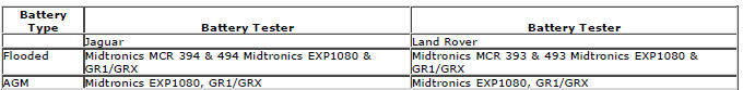
- AGM Batteries must be tested with a capable battery tester as detailed in the equipment section (Section 5) of this procedure.
NOTE: Under no circumstances should the battery be disconnected with the engine running because under these conditions the alternator can give a very high output voltage. This high transient voltage will damage the electronic components in the vehicle. Loose or incomplete battery connections may also cause high transient voltage.
3. HEALTH AND SAFETY PRECAUTIONS
WARNINGS: BATTERY CELLS CONTAIN SULPHURIC ACID AND EXPLOSIVE MIXTURES OF HYDROGEN AND OXYGEN GASES. IT IS THEREFORE ESSENTIAL THAT THE FOLLOWING SAFETY PRECAUTIONS ARE OBSERVED.
Batteries emit highly explosive hydrogen at all times, particularly during charging. To prevent any potential form of ignition occurring when working in the vicinity of a battery:
- Do not smoke when working near batteries.
- Avoid sparks, short circuits or other sources of ignition in the battery vicinity.
- Switch off current before making or breaking electrical connections.
- Ensure battery charging area is well ventilated.
- Ensure the charger is switched off when: a) connecting to a battery; b) disconnecting from the battery.
- Always disconnect the ground cable from the battery terminal first and reconnect it last.
Batteries contain poisonous and highly corrosive acid. To prevent personal injury, or damage to clothing or the vehicle, the following working practices should be followed when topping up, checking electrolyte specific gravity, removal, refitting or carrying batteries:
- Always wear suitable protective clothing (an apron or similar), safety glasses, a face mask and suitable gloves.
- If acid is spilled or splashed onto clothing or the body, it must be neutralized immediately and then rinsed with clean water. A solution of baking soda or household ammonia and water may be used as a neutralizer.
- In the event of contact with the skin, drench the affected area with water. In the case of contact with the eyes, bathe the affected area with cool clean water for approximately 15 minutes and seek urgent medical attention.
- If battery acid is spilled or splashed on any surface of a vehicle, it should be neutralized and rinsed with clean water.
- Heat is generated when acid is mixed with water. If it becomes necessary to prepare electrolyte of a desired specific gravity, SLOWLY pour the concentrated acid into water (not water into acid), adding small amounts of acid while stirring. Allow the electrolyte to cool if noticeable heat develops. With the exception of lead or lead-lined containers, always use non-metallic receptacles or funnels. Do not store acid in excessively warm locations or in direct sunlight.
Due to their hazardous contents, the disposal of batteries is strictly controlled. When a battery is scrapped, ensure it is disposed of safely, complying with local environmental regulations. If in doubt, contact your local authority for advice on disposal facilities.
4. BATTERY CARE REQUIREMENTS
4.1 RECEIPT OF A NEW VEHICLE
Within 24 hours of receipt of a new vehicle, a battery condition check must be carried out in accordance with the battery test process utilizing an appropriate tester as outlined in the equipment section (Section 5) of this procedure.
NOTE: The midtronics code must be recorded on the form.
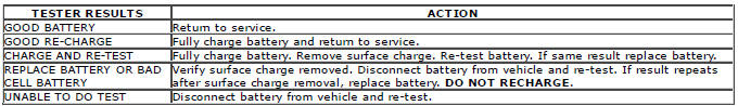
Any actions must be carried out in accordance with the table shown in the determining battery condition section (Section 6) of this procedure. The details must be recorded on the New Vehicle Storage Form which is part of the new vehicle storage document.
For additional information, refer to: New Vehicle Storage Form (100-11, Description and Operation).
4.2 NEW VEHICLE STORAGE
If the vehicle is to be stored the transit relays MUST be refitted and / or the vehicle put into transport mode.
Transit relay removal / vehicle placed in normal mode should only be completed a maximum of 72 hours prior to handover to customer For vehicles without either a transit mode or transit relay the battery negative cable must be DISCONNECTED from the battery.
The battery must be tested and/or re-charged every 30 days and MUST be re-charged after every 90 day period.
NOTE: The midtronics code must be recorded on the form.
Any actions must be carried out in accordance with the table shown in the determining battery condition section (Section 6) of this procedure. The details must be recorded on the New Vehicle Storage Form which is part of the new vehicle storage document.
For additional information, refer to: New Vehicle Storage Form (100-11, Description and Operation).
4.3 PDI / DELIVERY TO CUSTOMER
Before the vehicle is handed over to the customer and as part of the PDI, the condition of the battery needs to be confirmed. The battery condition must be checked in accordance with the battery test process utilizing an appropriate tester as outlined in the equipment section (Section 5) of this procedure.
NOTE: The midtronics code must be recorded on the form.
Any actions must be carried out in accordance with the table shown in the determining battery condition section (Section 6) of this procedure. The details must be recorded on the New Vehicle Storage Form which is part of the new vehicle storage document.
For additional information, refer to: New Vehicle Storage Form (100-11, Description and Operation).
4.4 REPLACEMENT BATTERIES FOR SERVICE
All service replacement batteries must have the battery condition checked within 24 hours of receipt and controlled on a 'First In First Out' basis to ensure batteries are not allowed to age unnecessarily.
For batteries in storage and not yet fitted to a vehicle, they must be stored in a dry environment, not in direct sunlight or under any direct heat source. Any batteries exhibiting any forms of damage or corrosion must not be fitted to any vehicle.
Any batteries which are dropped must be scrapped, this applies even if no external damage is apparent.
The battery condition must be checked every 30 days in accordance with the battery test process utilizing an appropriate tester as outlined in the equipment section (Section 5) of this procedure.
Any actions must be carried out in accordance with the table shown in the determining battery condition section (Section 6) of this procedure. The details must be recorded on the New Vehicle Storage Form which is part of the new vehicle storage document.
For additional information, refer to: New Vehicle Storage Form (100-11, Description and Operation).
4.5 BATTERY MAINTENANCE
Any battery whether it is in a vehicle or a replacement part must be tested and/or re-charged every 30 days and MUST be re-charged after every 90 day period.
4.6 BATTERY TEST PROCESS
It is recommended that this test is conducted at least 24 hours after the vehicle engine has been run or the battery charged to avoid the need of surface charge removal. If time constraints make this unacceptable then the surface charge must be removed.
Surface Charge Removal
A vehicle which has had its battery charged or been driven in a 24 hour period before the test, must have its surface charge removed.
- Turn on the ignition but do not start the vehicle
- Switch on the headlamps on high beam for a minimum 3 minutes
- Switch off the headlamps
- Wait a minimum of 5 minutes before recording test results for any battery measurements
Battery Test
The battery may be tested either on a bench or on the vehicle.
The battery condition must be checked in accordance with the battery test process utilizing an appropriate tester as outlined in the equipment section (Section 5) of this procedure.
NOTE: The midtronics code must be recorded on the form.
Any actions must be carried out in accordance with the table shown in the determining battery condition section (Section 6) of this procedure. The details must be recorded on the New Vehicle Storage Form which is part of the new vehicle storage document.
For additional information, refer to: New Vehicle Storage Form (100-11, Description and Operation).
CAUTION: DO NOT connect the tester to any other circuit or chassis point other than the battery negative terminal.
5. EQUIPMENT
All equipment used must be functionally capable of meeting the compliance requirements. Please refer to the approved equipment document.
In the case of batteries fitted to a new vehicle at the dealership, battery condition should be measured using the appropriate hand-held Midtronics tester as follows:
The test results must be recorded on the New Vehicle Storage Form which is part of the new vehicle storage document.
For additional information, refer to: New Vehicle Storage Form (100-11, Description and Operation).
NOTE: All equipment must be calibrated
6. DETERMINING BATTERY CONDITION
7. BATTERY CHARGING
It is essential that a suitably ventilated defined area exists in each dealership / retailer for battery charging.
CAUTION: It is very important that when charging batteries using the traction charger or other stand-alone chargers that the charger is set for the correct type of battery before charging commences. If the wrong switch is selected the result would be a battery that is not charged fully and / or overheating can occur. Follow the manufacturers operating instructions.
Batteries MUST BE tested and if necessary charged every 30 days and charged after 90 days irrespective of any test. It is recommended that dealers / retailers always have fully charged batteries ready for use.
CAUTION: Do not charge AGM batteries with voltages over 14.8 Volts as this will damage the battery.
A designated controlled area must be allocated for scrap batteries and clearly controlled as such.
To bring a discharged but serviceable battery back to a fully charged condition proceed as follows:
- Check and if necessary top-up the battery electrolyte level. (Flooded maintainable batteries only)
- Charge the battery using a charger as detailed in the approved equipment document following the manufacturers operating instructions.
NOTE: When using the Midtronics Diagnostic Charger, automatic mode must always be used. After charging and analysis, the charger may display 'Top-Off Charging', Hit STOP To End. Do not stop charging until the current falls to 5A or less, otherwise the battery will not be fully charged.
Following charging a post charge battery condition test must be carried out in accordance with the table shown in the determining battery condition section (Section 6) of this procedure.
NOTE: The midtronics code must be recorded on the form.
Any actions must be carried out in accordance with the table shown in the determining battery condition section (Section 6) of this procedure. The details must be recorded on the New Vehicle Storage Form which is part of the new vehicle storage document.
For additional information, refer to: New Vehicle Storage Form (100-11, Description and Operation).
8. BATTERY REPLACEMENT
If it is determined that a battery requires replacement, always refer to the appropriate section of the workshop manual for instructions on removing and installing the battery from the vehicle.
On in service vehicles fitted with a Battery Monitoring System (BMS), the BMS module must be reset following the installation of a new battery. The BMS module reset procedure must be performed using an approved diagnostic system.
9. CONFIRMING ELECTROLYTE LEVEL
WARNINGS: BEFORE CHECKING AND TOPPING-UP THE BATTERY ELECTROLYTE, REFER TO THE HEALTH AND SAFETY PRECAUTIONS SECTION.
AGM TECHNOLOGY BATTERIES ARE FULLY SEALED FOR LIFE AND NO ATTEMPT SHOULD BE MADE TO CHECK OR TOP UP THE ELECTROLYTE LEVEL.
On certain types of battery the electrolyte level may need to be checked.
- Make sure the battery is of a type suitable for topping up. These types of batteries will have cell plugs visible on the top face of the battery or a removable access panel to allow access to the cells.
- On batteries with a clear or opaque case and level marks, check the electrolyte level by visual inspection of the maximum level indicator mark on the battery casing indicating adequate level above the battery separators.
- On batteries with black cases, remove the cell plugs or access panel and ensure the electrolyte level is level with the indicator in the cell hole. A flashlight may be required to see the electrolyte level on this type of battery.
- If the electrolyte level is low, top-up using distilled water.
NOTE: Maintenance free and Valve Regulated (AGM) batteries are sealed and therefore cannot be topped up.
CAUTION: DO NOT overfill.
Quiescent Drain
VEHICLE QUIESCENT CURRENT TESTING
On vehicles fitted with a Battery Monitoring System (BMS), the diagnostic routine for quiescent drain testing in the approved Jaguar or Land Rover diagnostic system should be utilized.
If a customer complains of a vehicle battery that discharges continuously or when left for a prolonged period of time, it is recommended that a quiescent drain test is performed as described below.
The battery drain should be measured using the approved Jaguar or Land Rover diagnostic system or a Digital Multi-Meter (DVOM). A procedure for quiescent drain measurement using the diagnostic system is available in the Diagnosis and Testing section of the Workshop Manual. The vehicle should be in the locked/armed state (for example vehicle alarm fully armed), all doors, engine and luggage compartment lids are open and latched (so as to appear closed from an electrical point of view). The test should take place after the vehicle has entered shutdown mode. The time taken for this to occur after the ignition is switched off varies according to model (Refer to the Topix On line resource for details).
When the vehicle is armed, the effect of the security system Light Emitting Diode (LED) flashing is to cause a pulsation in the measured current drain. In this case, either the average current should be taken (using a Digital Multi- Meter (DVOM) with an averaging system) or the current reading taken, ignoring the brief high current peaks.
EQUIPMENT
Approved Jaguar or Land Rover diagnostic system with current probe OR Digital Multi-Meter (DVOM) with current probe.
METHOD OF MEASUREMENT
Using an Approved Jaguar or Land Rover Diagnostic System.
- Switch off all electrical loads and ensure that the ignition is off
- Connect the current probe to the approved Jaguar or Land Rover diagnostic system
- Calibrate the probe
- Install a clamp around the battery lead/junction box lead
- Go to the Quiescent Current Testing section in this procedure
Using a digital multimeter
Do not use an in-line DVOM to measure the quiescent drain on vehicles fitted with an electronic throttle (for example Range Rover 2002MY onwards). The current exceeds the maximum amount the fuse in the DVOM is capable of handling.
- Switch off all electrical loads and ensure that the ignition is off
- Connect the current probe to the digital multmeter
- Calibrate the probe
- Install a clamp around the battery lead/junction box lead
- Go to the Quiescent Current Testing section in this procedure
QUIESCENT CURRENT TESTING
- Switch ignition to 'on' or select ignition mode in keyless vehicles and switch to 'off' (do not crank)
- Remove key from ignition switch (if equipped)
- Open and latch all doors, hood and luggage compartment lid
- Lock the vehicle using the remote function on the remote handset. (Single lock only to avoid volumetric alarm arming)
- Remove any other potential electrical drains such as accessories plugged into accessory sockets
- Record the amperage readings after the shutdown period referenced in the Topix on line resource for details. Note all cars from 10MY onwards should be less than 30mA after 30 minutes
- Record the final reading on the battery report form
The preferred method of testing following an excessive current consumption figure is to use a current probe around individual junction box leads to the various suspected circuits to identify a potential cause. This is in preference to the old method of removing fuses for the following reasons:
- The drain may be caused by a module remaining active and preventing the quiescent drain from reducing to normal levels
- The drain may be caused by a relay winding that is activated. Pulling the fuse can allow this to 'reset' and the drain will be lost and go un-diagnosed
Land Rover Quiescent Drain Values
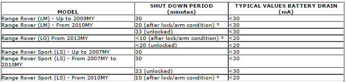
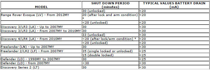
NOTE:
1. The total current drain will be higher if certain approved accessories are fitted (for example: tracker, trailer module, etc.)
2. Applies to vehicles without Tire Pressure Monitoring System (TPMS). Vehicle shut-down period with TPMS is approximately 15 minutes.
Charging System
Principle of Operation
For battery condition indicator information, refer to the relevant section of the workshop manual.
The generator is a 'smart' system, able to allow for temperature variations and optimize battery charging.
For information on the description and operation of the system, generator and regulator section of the workshop manual.
Inspection and Verification
CAUTION: Diagnosis by substitution from a donor vehicle is NOT acceptable. Substitution of control modules does not guarantee confirmation of a fault and may also cause additional faults in the vehicle being checked and/or the donor vehicle.
NOTE: Check and rectify basic faults before beginning diagnostic routines involving pinpoint tests.
1. Verify the customer concern.
2. Visually inspect for obvious mechanical or electrical faults.
Visual inspection
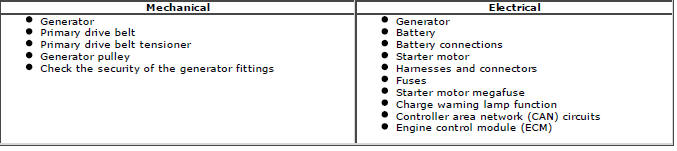
3. If an obvious cause for an observed or reported concern is found, correct the cause (if possible) before proceeding to the next step.
4. Use the approved diagnostic system or a scan tool to retrieve any diagnostic trouble codes (DTCs) before moving onto the symptom chart or DTC index.
- Make sure that all DTCs are cleared following rectification.
5. Check DDW for open campaigns. Refer to the corresponding bulletins and SSM's which may be valid for the specific customer complaint and carry out the recommendations as needed.
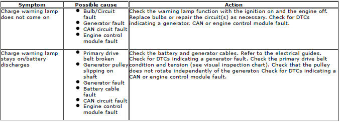
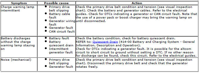
Symptom chart
DTC index
For a complete list of all diagnostic trouble codes (DTCs) that could be logged on this vehicle.
READ NEXT:
 Battery - Diagnosis and Testing
Principles of Operation
For a detailed description of the battery system and operation, refer to the
relevant Description and Operation section of
the workshop manual. REFER to: (414-01 Battery, Moun
Battery and Cables AWD
Component
Location
COMPONENT LOCATION - SHEET 1 OF 2 - DW12c
CJB (central junction box)
ECM (engine control module)
RJB (rear junction box)
Battery
BJB (battery junction box)
Starter motor
Ge
SEE MORE:
Important information
The information contained in this handbook covers all vehicle derivatives and
optional equipment,
some of which may not be fitted to your vehicle. Due to printing cycles, this
handbook may include
descriptions of options before they become generally available.
The vehicle options, hardware an
Symbols used in this handbook
Safety warnings indicate either a procedure which must be followed
precisely, or
information that should be considered with great care, in order to avoid the
possibility
of personal injury.
Cautions indicate either a procedure which must be followed precisely, or
information that
should
