Range Rover Evoque: Battery and Cables AWD
Component Location
COMPONENT LOCATION - SHEET 1 OF 2 - DW12c
- CJB (central junction box)
- ECM (engine control module)
- RJB (rear junction box)
- Battery
- BJB (battery junction box)
- Starter motor
- Generator
COMPONENT LOCATION - SHEET 2 OF 2 - GTDi
- CJB
- ECM
- RJB
- Battery
- BJB
- Starter motor
- Generator
Overview
OVERVIEW
The battery is located behind a cover on the LH (left-hand) side of the engine compartment. The battery sits in a tray and is secured in position with a clamp plate and bolt assembly. The battery supplies electrical power to the starter motor, generator and BJB (battery junction box).
The BJB is mounted adjacent the LH front suspension turret. The BJB contains fusible links, blade and J-case fuses, and relays to distribute electrical power to various vehicle systems and junction boxes.
NOTE: The fusible links are mounted on the inboard side of the BJB behind a series of removable covers.
The CJB (central junction box) is mounted behind the glovebox and receives its main power supply from the BJB. In addition to containing blade fuses, the CJB is the main controller for a number of vehicle systems. These functions are outlined in the relevant sections of this manual.
System Operation and Component Description
Control Diagram
NOTE: A = Hardwired connection; D = High speed CAN (controller area network) bus; O = LIN (local interconnect network) bus
SHEET 1 OF 2 - DW12c
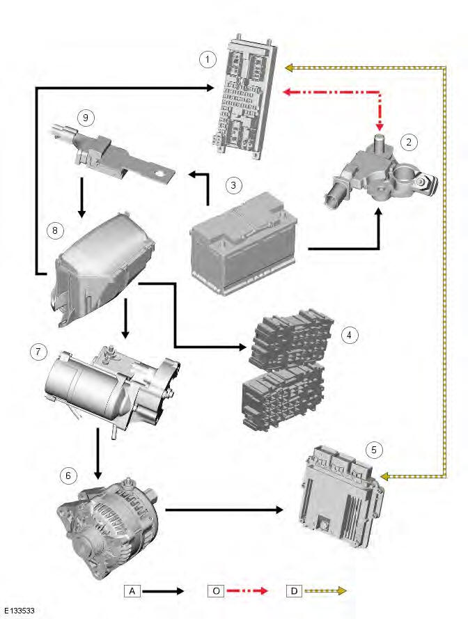
- CJB (central junction box)
- Battery monitoring system (BMS) module
- Battery
- RJB (rear junction box)
- ECM (engine control module)
- Generator
- Starter motor
- BJB (battery junction box)
- Starter fuse
SHEET 2 OF 2 - GTDi
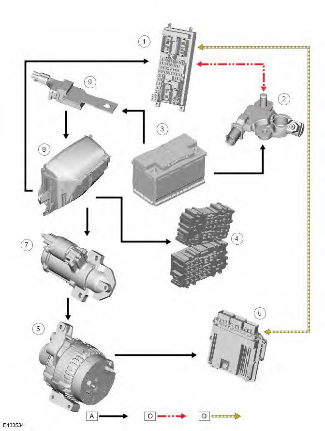
- CJB
- Battery monitoring system (BMS) module
- Battery
- RJB
- ECM
- Generator
- Starter motor
- BJB
- Starter fuse
System Operation
Starter Fuse
Incorporated in the cable between the battery and the starter motor/generator is a CAL3 starter fuse. The fuse is mounted adjacent the battery positive terminal and is integral with the cable assembly. In the event of fuse failure, the complete cable assembly must be replaced.
Wire Color Codes
New wire color codes have been introduced in the Electrical Circuit Diagrams. These new codes are shown in the table below.
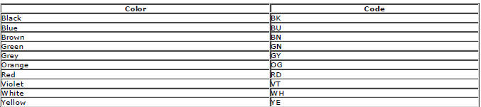
Tracer wire color codes are separated from the main wire color code by a hyphen, thus BU-RD equates to a blue wire with a red tracer. For more information, refer to the Electrical Circuit Diagrams and the Electrical Library.
POWER MODES
The CJB controls the power supplies for the various vehicle functions. There are 9 power modes available which are used by various systems to determine the operating condition of the vehicle. Only 3 of these modes will be noticeable to the driver and technicians as follows:
- Power mode 0 - Ignition off
- Power mode 4 - Accessory
- Power mode 6 - Ignition
- Power mode 7 - Engine running
- Power mode 9 - Crank.
Transport Mode
All new vehicles will be delivered from the factory in transport mode. Transport mode replaces the traditional transit relay and inhibits a number of electrical systems and features to eliminate quiescent drain from the battery during delivery.
Transport mode also inhibits some electrical loads when the engine is running to ensure that the battery is never discharged while the engine is running.
When the vehicle is in transport mode 'transp' will be displayed in the instrument cluster odometer.
To remove the vehicle from transport mode, the Land Rover approved diagnostic system must be connected during the Pre-Delivery Inspection (PDI). For more information, refer to the PDI manual.
Stop/Start System Component Location
- Voltage quality module
- BMS module
- Absorption glass mat battery
Component Description
Absorption Glass Mat Battery
To counteract the extreme power consumption of a Stop/Start system and/or the Park Heat feature, a high-performance battery based on Absorption Glass Mat technology has been introduced. The battery owes its superiority over a conventional battery to the 'absorbent glass mat' which is a fine fiberglass mat compressed between the lead plates. Refer to: Starting System - AWD (303-06A Starting System - TD4 2.2L Diesel, Description and Operation).
Battery Monitoring System
The Battery Monitoring System (BMS) was introduced due to fuel economy benefits, battery life optimization and enhanced diagnostics.
Moreover, optimal battery health is a fundamental factor in the correct operation of the Stop/Start system. Therefore, the BMS calculates and communicates the battery status.
BMS Plate
- BMS plate
The BMS plate is a metal plate that is bolted on top of the BMS unit on the battery negative terminal. The plate is used to secure the battery negative cables and the ECM earth to the battery negative terminal.
Voltage Quality Module
During an engine Stop/Start cycle the Voltage Quality Module (VQM) maintains some of the vehicle's electrical systems by supplying a support voltage around the vehicle's electronic components during an engine restart. This allows crucial vehicle systems to continue uninterrupted when there is a sudden draw of current from the battery.
READ NEXT:
 Battery - Removal and Installation
Removal
NOTES:
Removal steps in this procedure may contain installation details.
Some variation in the illustrations may occur, but the essential information is
always correct.
1.
2.
3. Torque: 25
Battery Tray
Removal
NOTES:
Removal steps in this procedure may contain installation details.
Some variation in the illustrations may occur, but the essential information is
always correct.
1. Refer to: Battery
Generator and Regulator - GTDi 2.0L Petrol
Generator - Component
Location
COMPONENT LOCATION
Battery positive connection
LIN (local interconnect network) bus connection
Generator
Generator - Overview
OVERVIEW
A single self-exciting gener
SEE MORE:
Important information
The information contained in this handbook covers all vehicle derivatives and
optional equipment,
some of which may not be fitted to your vehicle. Due to printing cycles, this
handbook may include
descriptions of options before they become generally available.
The vehicle options, hardware an
Symbols used in this handbook
Safety warnings indicate either a procedure which must be followed
precisely, or
information that should be considered with great care, in order to avoid the
possibility
of personal injury.
Cautions indicate either a procedure which must be followed precisely, or
information that
should
