Range Rover Evoque: Generator and Regulator - GTDi 2.0L Petrol
Generator - Component Location
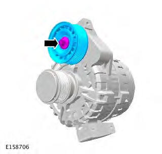
COMPONENT LOCATION
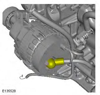
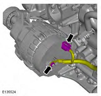
- Battery positive connection
- LIN (local interconnect network) bus connection
- Generator
Generator - Overview
OVERVIEW
A single self-exciting generator is located at the front of the engine on the LH (left-hand) side of the cylinder block. There is one generator available for the petrol engines. The generator is rated at 180 amps.
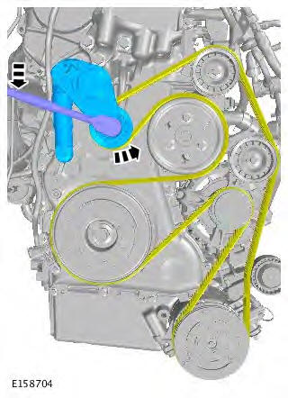
The generator pulley incorporates a one-way clutch that reduces NVH (noise, vibration and harshness), and improves the life of the accessory drive belt. The one-way clutch allows the belt to drive the pulley without slip occurring, but prevents the generator from driving the belt during transients in engine speed ('belt whip') due to the high rotational inertia of the generator internal components.
The generator comprises the following major components:
- Stator
- Rotor
- Rectifier pack
- Regulator.
The stator consists of a flat core pack into which the stator wires are pressed.
The rotor comprises a field winding, wound around an iron core and mounted on a shaft. The rotor is housed within the stator and mounted on bearings to provide smooth running and support, due to the side loading applied by the drive belt tension.
The rectifier contains 3 pairs of diodes (three on the positive plate and three on the negative plate) mounted on a heat sink. The heat sink dissipates the resultant heat created in the electrical conversion process. The rectifier converts the AC (alternating current) produced in the stator coils into DC (direct current) that is required by the vehicle electrical system.
The regulator provides a controlled variable voltage output from the generator. Two electrical terminals are provided on the outer casing of the generator. B+ terminal supplies the rectified and regulated DC from the generator, via a large diameter cable to the battery positive terminal. The second terminal provides the LIN (local interconnect network) bus connection between the regulator and the ECM (engine control module).
The regulator is connected via LIN bus to the ECM, the ECM is also connected via the high speed CAN (controller area network) bus to the CJB (central junction box). The CJB receives information from the BMS regarding battery conditions.
The CJB uses the information from the BMS to set the target voltage via high speed CAN to the ECM, then the ECM sends it via LIN to the alternator.
The LIN bus is also used to communicate a mechanical failure, or fault in the wiring and connections from the generator to the ECM. A DTC (diagnostic trouble code) is stored in the ECM and if necessary, the charge warning indicator lamp is illuminated in the instrument cluster after a short delay.
During engine starting the charge warning indicator lamp is illuminated in the instrument cluster when the ignition is energized, and is extinguished when the engine starts and the ECM detects a generator output voltage.
Generator and Regulator - GTDi 2.0L Petrol
Torque Specifications
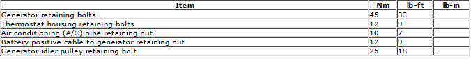
Generator
Removal
NOTES:
Removal steps in this procedure may contain installation details.
Some variation in the illustrations may occur, but the essential information is always correct.
1. Disconnect the battery ground cable.
Refer to: Specifications (414-01 Battery, Mounting and Cables, Specifications).
2. WARNING: Make sure to support the vehicle with axle stands. Raise and support the vehicle.
3. Refer to: Cooling System Partial Draining, Filling and Bleeding (303-03B Engine Cooling - GTDi 2.0L Petrol, General Procedures).
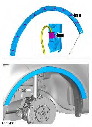
4. CAUTION: Take extra care not to damage the component.
NOTE: LH illustration shown, RH is similar.
Remove the RH front fender trim panel.
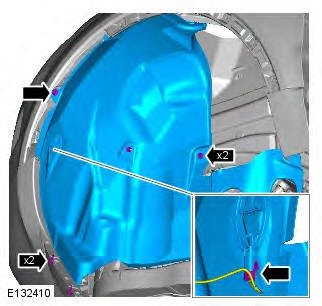
5. NOTE: LH illustration shown, RH is similar.
Remove the forward section of the RH front wheel arch liner.
6.
7. Lower the vehicle.
8. Refer to: Intake Manifold (303-01B Engine - GTDi 2.0L Petrol, Removal and Installation).
9.
10.
11. Torque: 12 Nm
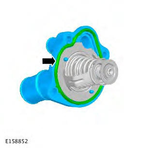
12. NOTES: Remove and discard the seal.
Install a new seal.
13.
14. Torque: 12 Nm
15. Torque: 45 Nm
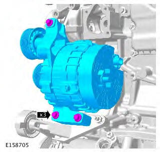
16. NOTE: Do not disassemble further if the component is removed for access only.
Torque: 25 Nm
Installation
1. To install, reverse the removal procedure.
Generator
Control Diagram
NOTE: A = Hardwired; D = High speed CAN (controller area network) bus; O = LIN (local interconnect network) bus.
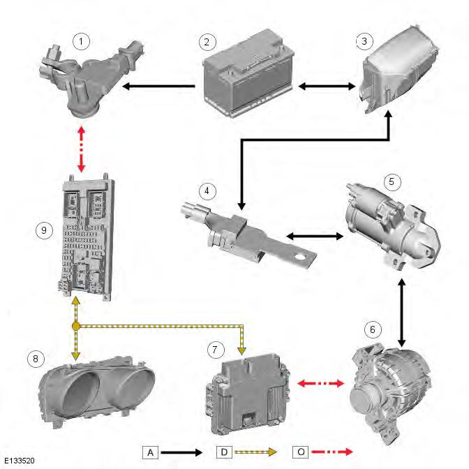
- Battery Monitoring System (BMS)
- Battery
- Battery Junction Box (BJB)
- Starter fuse
- Starter motor
- Generator
- Engine Control Module (ECM)
- Instrument cluster
- Central Junction Box (CJB)
System Operation
Smart Regenerative Charging
A smart regenerative charging system increases the alternator output when the vehicle brakes or decelerates. This converts the kinetic energy of the vehicle into electric energy without having to use additional fuel.
The smart regenerative feature is allowed to operate within certain environmental constraints to ensure the feature delivers the greatest benefit possible whilst maintaining system integrity.
The 'free' electric energy is captured by charging the battery above the target level. This energy can be used by the electrical systems at a later stage. This could be when the engine is switched off during a stop-phase, but can also be when the generator is operating in a less efficient mode.
The battery state of charge can be corrected both up and down to achieve the most appropriate level to maximize the benefit of the smart regenerative charging feature. If the ECM (engine control module) decides there is recoverable energy available, then the alternator charge setpoint will be overridden and the extra system voltage will allow the battery to consume a proportion of the recoverable energy. If the battery is at a high state of charge then some of the additional energy can be used to contribute by means of load reduction when there is a significant torque demand on the engine. By monitoring which loads are active and altering both the ultimate voltage levels and the rate at which they are changed any visible effects of the feature operating are minimized.
Component Description
Battery Monitoring System (BMS)
This system monitors various battery parameters. There are directly measured and predictive values. Battery current and voltage are the result of direct measurement, while state of charge (SoC), state of function (SoF) and electrolyte temperature are predicted values. These signals are used by both the charging system and the stop/start system to ensure the vehicle functions are optimized. The measurement is autonomous and happens in all states to enable an accurate condition of the battery to be assessed at all times. Software based values are calculated and used as a backup in the event of a system fault condition. If any of the measured/predicted values do not meet the necessary thresholds, the stop/start feature will be suspended until the thresholds are met. In the case of a fault condition, the stop/start system will be disabled for the duration of the particular drive cycle. DTC (diagnostic trouble code)'s relating to the faults will be stored in the CJB (central junction box).
Generator
Principles of Operation
For further information, REFER to: Charging System (414-00 Battery and Charging System - General Information, Diagnosis and Testing).
REFER to: Charging System (414-00 Battery and Charging System - General Information, Diagnosis and Testing).
READ NEXT:
 Exterior Lighting - Component Location
COMPONENT LOCATION
Instrument cluster
Hazard flasher switch
Rain/Light sensor
Rear height sensor (Xenon headlamps only)
Side turn signal indicator lamp
Headlamp leveling control module
CJB (c
SEE MORE:
Important information
The information contained in this handbook covers all vehicle derivatives and
optional equipment,
some of which may not be fitted to your vehicle. Due to printing cycles, this
handbook may include
descriptions of options before they become generally available.
The vehicle options, hardware an
Symbols used in this handbook
Safety warnings indicate either a procedure which must be followed
precisely, or
information that should be considered with great care, in order to avoid the
possibility
of personal injury.
Cautions indicate either a procedure which must be followed precisely, or
information that
should
