Range Rover Evoque: Instrument Cluster
Instrument Cluster - Component Location
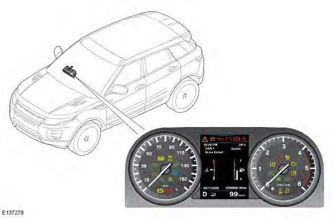
COMPONENT LOCATION
Instrument Cluster - Overview
OVERVIEW
The instrument cluster comprises two analogue gages for the speedometer and the tachometer and a 5 inch Thin Film Transistor (TFT) display for driver information.
The analogue gages are electronically driven using vehicle speed information from the ABS (anti-lock brake system) module for the speedometer and engine speed signals from the ECM (engine control module) for the tachometer. The information is passed to the instrument cluster from the modules on the high speed CAN (controller area network) bus.
The speedometer is located on the LH (left-hand) side of the cluster and is available in three market variants:
- Major scale Miles Per Hour (MPH) UK Diesel and Petrol
- Major scale Miles Per Hour (MPH) US Petrol
- Major scale KM/H ROW Diesel and Petrol.
The secondary speedometer is a digital display in the TFT. In most markets, the displayed units shown can be toggled via the "units" option in the Trip computer menu.
The tachometer is located on the RH (right-hand) side of the cluster and is available in two Revolutions Per Minute (RPM) displays: one for petrol models and one for diesel models.
- Petrol models with a maximum engine speed of 8000 RPM
- Diesel models with a maximum engine speed of 6000 RPM.
The TFT screen displays vehicle related information to the driver, for example; engine temperature, fuel level, gear position, Terrain Response mode, cruise control and Hill Descent Control (HDC).
Driver information is also displayed, for example; navigation turn-by-turn information, voice control, trip computer information and basic audio details.
The gauges are illuminated in a pure white color, but change to a red color when Dynamic mode is selected.
The instrument cluster features a number of warning indicators. The warning indicators illuminate in one of four colors which indicate the level of importance of the warning as follows:
- Red = Warning
- Amber = Caution
- Green = System operative
- Blue = Headlamp high beam operative.
A vehicle information and settings menu is available to allow the driver to select certain features and functions of the vehicle, instrument cluster, trip computer and service information and change them to their personal preference. A menu control 'joy pad' is located on the RH side of the steering wheel and allows selection of the displayed functions and navigation of the menus. When selected, the menu is displayed in the TFT screen.
System Operation and Component Description
Control Diagram
NOTE: A = Hardwired; D = High Speed CAN bus; N = Medium Speed CAN bus; O = LIN bus
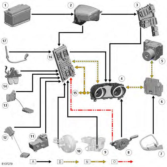
- Battery
- Battery Junction Box (BJB)
- Rear Junction Box (RJB)
- Instrument cluster
- Anti-lock Brake System (ABS) module
- Engine Control Module (ECM)
- Ambient temperature sensor
- Steering wheel module
- Washer reservoir level sensor
- Brake reservoir level sensor
- Electric steering column lock
- Left Hand (LH) fuel level sensor
- Right Hand (RH) fuel level sensor
- Tail door latch motor
- To other vehicle systems
- Central Junction Box (CJB)
- Engine coolant level sensor
System Operation
OPERATION
The instrument cluster receives a permanent battery voltage supply via a fuse in the RJB (rear junction box). High speed and medium speed CAN (controller area network) buses are also connected to the instrument cluster to receive information from other system control modules for instrument cluster functions.
The speedometer is driven by high speed CAN signals transmitted by the ABS (anti-lock brake system) module. The wheel speeds are measured by sensors reading the rotational speed of the wheels from toothed targets on the hubs. The wheel speeds are passed from the sensors to the ABS module in the form of pulsed signals. The ABS module converts these signals into a speed output on the high speed CAN to the instrument cluster.
The tachometer is driven by an engine speed signal transmitted on the high speed CAN from the ECM (engine control module). The signal is derived from the CKP (crankshaft position) sensor. The signal is received by the instrument cluster microprocessor and the output from the microprocessor drives the tachometer.
The steering column lock is connected directly to the instrument cluster. The steering wheel switches are also connected directly to the instrument cluster via the steering wheel module. Other vehicle sensors are connected to the CJB (central junction box) which processes the signals from the sensors and passes them to the instrument cluster on the high speed or medium speed CAN bus. The ambient temperature signal is received by the ECM which processes the signal and passes the information to the instrument cluster on the high speed CAN bus.
Component Description
DESCRIPTION
INSTRUMENT CLUSTER
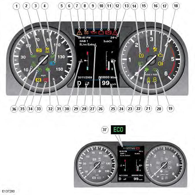
- Side lamps on warning indicator
- Anti-lock Brake System (ABS) warning indicator
- Adaptive front lighting system warning indicator
- Hill Descent Control (HDC) warning indicator (not applicable to front wheel drive vehicles)
- High beam warning indicator
- Clock display
- General warning/information message indicator (amber)
- Glow plug warning indicator (diesel models only)
- Low oil pressure warning indicator
- Battery charge warning indicator
- Parking brake applied warning indicator (Symbol shown as 'PARK' in NAS markets)
- Critical warning indicator (red)
- Ambient temperature display
- Tire Pressure Monitoring System (TPMS) warning indicator
- Seat belt warning indicator
- Airbag/SRS warning indicator
- Engine Malfunction Indicator Lamp (MIL)
- Rear fog lamps active warning indicator
- Trailer turn signal indicators warning indicator
- Dynamic Stability Control (DSC) warning indicator
- Dynamic Stability Control (DSC) off warning indicator
- Right Hand (RH) turn signal indicator
- Front fog lamps active warning indicator
- Fuel level gage
- Trip computer information display
- Odometer
- Message center
- Terrain Response mode indicator (not applicable to front wheel drive vehicles)
- Selected gear display
- Engine coolant temperature gage
- Alarm system Light Emitting Diode (LED)
- Left Hand (LH) turn signal indicator
- Low brake fluid or Electronic Brake Distribution fault warning indicator (red) (Symbol shown as 'BRAKE' in NAS markets)
- Low brake pads or Emergency Brake Assist (EBA) fault warning indicator (amber) (Symbol shown as 'BRAKE' in NAS markets)
- Cruise control active warning indicator
- Auto high beam enabled warning indicator
- Stop/Start (ECO) active warning indicator
ANALOGUE INSTRUMENTS
The analogue instruments located in the instrument cluster are as follows:
- Speedometer
- Tachometer.
The speedometer and tachometer are each driven by an electronic stepper motor. The characteristics of this type of motor produce damping of the pointer needle. Both of the gages return to their respective zero positions when the ignition is switched off.
Speedometer
The speedometer is driven by square wave signals derived from the wheel speed sensors and the ABS module. The signal is received via the ECM on the high speed CAN bus.
Tachometer
The tachometer is driven by an engine speed signal transmitted on the high speed CAN from the ECM. The signal is derived from the CKP sensor.
MESSAGE CENTER
Refer to: Information and Message Center (413-08 Information and Message Center, Description and Operation).
WARNING INDICATORS
The warning indicators are located in various positions in the instrument cluster. The warning indicators can be split into two groups; self controlled and externally controlled.
Self controlled warning indicators are dependent on software logic within the instrument pack for activation. The pack software controls the indicator check illumination at ignition on and all indicators whose operation is controlled by the instrument cluster, the low fuel level warning indicator for example.
Externally controlled indicators are supplied with current from another system controlling module or illuminated by the instrument cluster on receipt of a bus message from another subsystem module.
Some indicators are activated by an external subsystem module but the instrument cluster contains the control logic.
DIAGNOSTICS
Car Configuration File (CCF)
The Car Configuration File (CCF) contains all relevant data about the specification and market condition of the applicable vehicle, immobilisation codes and driver personal settings. This information is retained in the CJB and is read by the instrument cluster, enabling the cluster to detect which systems and components are fitted to the vehicle. This information is continuously sent to the instrument cluster on the medium speed CAN bus. The instrument cluster also backs up the CCF in it's internal memory.
The CCF will also need to be updated using an approved Land Rover diagnostic system if the vehicle is modified in service from its original factory specification. This can include fitting non-standard wheels and/or tyres, optional accessory dealer fit components with an electrical interface, i.e. park distance control.
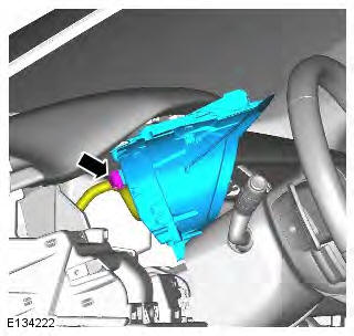
Instrument Cluster
Removal
NOTES: When a new instrument cluster is to be installed, the Land Rover approved diagnostic system must be connected to the vehicle and the instrument cluster renewal procedure followed.
Removal steps in this procedure may contain installation details.
1. Disconnect the battery ground cable.
Refer to: Specifications (414-01 Battery, Mounting and Cables, Specifications).
2. Refer to: Driver Side Register (412-01 Climate Control, Removal and Installation).
3. Torque: 1.5 Nm
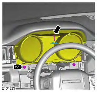
4. CAUTION: Take extra care not to damage the instrument cluster face.
Installation
1. To install, reverse the removal procedure.
Instrument Cluster

Principles of Operation
For a detailed description of the instrument cluster operation, refer to the relevant description and operation section in the workshop manual. REFER to: (413-01 Instrument Cluster)
Data is provided to the instrument cluster from other subsystem modules in the form of controller area network (CAN) messages. The instrument cluster identifies the signals and displays the appropriate message in the message center. Most messages are accompanied by a chime or series of chimes which are requested by the module generating the message.
The driver can view system status messages which are current within the instrument cluster software by pressing and holding the trip reset button for more than three seconds, the information display will then display the current messages in priority order. For more information, refer to the relevant workshop manual section.
Car Configuration File (CCF)
CAUTION: If a new instrument cluster is to be installed, the instrument cluster renewal procedure must be carried out using the approved diagnostic system. This will ensure that the CCF data is correctly transferred from the central junction box (CJB) to the replacement cluster. The CCF will also need to be updated using the approved diagnostic system if the vehicle is modified in service from its original factory specification. This can include the fitting of non-standard wheels and/or tires and optional accessory dealer install components with an electrical interface, such as park distance control.
The CCF contains all relevant data about the specification and market condition of the applicable vehicle, immobilization codes and driver personal settings. This information is retained in the CJB, the engine control module (ECM) and the instrument cluster enabling each system module to detect which systems and components are installed to the vehicle. The information is continuously transferred between these three system modules to ensure that the data is constantly backed-up between the modules.
Inspection and Verification
CAUTION: Diagnosis by substitution from a donor vehicle is NOT acceptable. Substitution of control modules does not guarantee confirmation of a fault and may also cause additional faults in the vehicle being checked and/or the donor vehicle.
1. Verify the customer concer
2. Confirm which, if any, warning lights and/or messages were displayed on the instrument cluster. For a list of messages, refer to workshop manual section 413-08 - Information and Message Center.
REFER to: Information and Message Center (413-08 Information and Message Center, Description and Operation).
3. Visually inspect for obvious electrical faults.
Visual inspection
- Battery
- Fuses
- Central, engine and battery junction boxes
- Megafuses
- Wiring harness
- Damaged, loose or corroded connectors
- Controller area network (CAN) circuits
- Instrument cluster
- Central junction box (CJB)
- Engine control module (ECM)
4. If an obvious cause for an observed or reported concern is found, correct the cause (if possible) before proceeding to the next step.
5. Use the approved diagnostic system or a scan tool to retrieve any DTCs before moving onto the DTC index.
- Make sure that all DTCs are cleared following rectification.
6. Check DDW for open campaigns. Refer to the corresponding bulletins and SSM's which may be valid for the specific customer complaint and carry out the recommendations as needed.
DTC index
For a complete list of all diagnostic trouble codes that could be logged on this vehicle, please refer to section 100-00.
Horn
Removal
NOTE: Removal steps in this procedure may contain installation details.
1.
2. Torque: 10 Nm
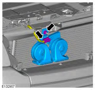
Installation
1. To install, reverse the removal procedure.
Horn
Torque Specifications

READ NEXT:
 Information and Message Center
Information and Message Center -
Component Location
COMPONENT LOCATION
Information and Message Center -
Overview
OVERVIEW
The message center is located in the instrument cluster, in a central
positio
Warning Devices
Warning Devices - Component Location
Component Location - Blind Spot Monitoring System
Battery
Voltage quality module
CJB (central junction box)
RH (right-hand) door mirror
RH blind spot monito
SEE MORE:
Important information
The information contained in this handbook covers all vehicle derivatives and
optional equipment,
some of which may not be fitted to your vehicle. Due to printing cycles, this
handbook may include
descriptions of options before they become generally available.
The vehicle options, hardware an
Symbols used in this handbook
Safety warnings indicate either a procedure which must be followed
precisely, or
information that should be considered with great care, in order to avoid the
possibility
of personal injury.
Cautions indicate either a procedure which must be followed precisely, or
information that
should
