Range Rover Evoque: Warning Devices
Warning Devices - Component Location
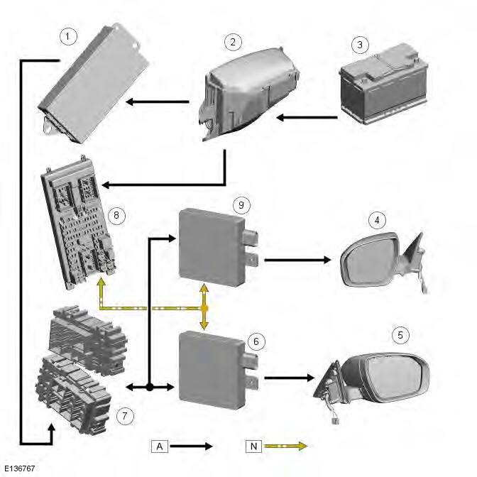
Component Location - Blind Spot Monitoring System
- Battery
- Voltage quality module
- CJB (central junction box)
- RH (right-hand) door mirror
- RH blind spot monitoring module
- RJB (rear junction box)
- LH (left-hand) blind spot monitoring module
- LH door mirror
- BJB (battery junction box)
Warning Devices - Overview
Overview - Blind Spot Monitoring System
Eliminating blind spots is a major element in vehicle body design, but because of the structural requirements of B, C and D pillars, blind spots cannot be entirely eliminated. Statistics show that some accidents are directly attributable to drivers moving across into the path of overtaking vehicles that have not been seen in conventional mirrors. New mirror designs have improved the situation, but by remotely covering areas that cannot be seen either directly or by the vehicle mirrors, have led to the introduction of a radar-based blind spot monitoring system.
The blind spot monitoring system comprises:
- LH (left-hand) Blind spot monitoring sensor
- RH (right-hand) Blind spot monitoring sensor
- LH door mirror
- RH door mirror
The system uses two radar modules operating at a frequency of 24 GHz and each combining the radar face and electronic module in a single unit. The modules are located behind the rear bumper surface, symmetrically, one on each side of the car behind the rear wheels. They are side facing and inclined rearwards at an angle of 25 degrees, which is dictated by the shape at the rear of the vehicle. Each module is calibrated to detect a vehicle in the driver's blind spot. Once a vehicle is detected the module illuminates an amber warning 'alert icon' LED (light emitting diode) in the relevant exterior door mirror. If there is a fault or blockage with the blind spot monitoring system an amber warning status icon indicator dot LED is displayed in the exterior mirror and the message 'blind spot monitoring not available' or 'blind spot sensor blocked' is displayed in the instrument cluster message center.
When the system initiates, it performs a self-check, during which the warning icons in the mirrors illuminate alternately for a short period of time. Each module does a left/right determination check when the ignition is switched on. Each mirror has a different circuit configuration so that the modules can determine which mirror they are connected to. If a module detects the wrong mirror, it will go into a fault condition.
The blind spot monitoring modules receive vehicle speed on the medium speed CAN (controller area network) and are inactive until the vehicle reaches 16kph (10mph).
Each Blind Spot Monitor module emits a radar field greater than the blind spot area. The actual blind spot area is calibrated into the module during its manufacture.
CAUTION: The blind spot monitoring system is designed as a driver aid not a safety device. The driver should always exercise due care and attention whilst driving.
Warning Devices - System Operation and Component Description
Control Diagram
NOTE: A = Hardwired; N = Medium Speed CAN (controller area network) bus
- Voltage quality module
- BJB (battery junction box)
- Battery
- LH (left-hand) door mirror
- RH (right-hand) door mirror
- LH blind spot monitoring module
- RJB (rear junction box)
- CJB (central junction box)
- RH blind spot monitoring modul
System Operation
Blind Spot Monitor (BSM)
CAUTIONS:
Ensure that the warning indicators in the exterior mirrors are not obscured by stickers or other objects.
Do not attach stickers or objects to the rear bumpers that may interfere with the radar sensors.
The purpose of the blind spot monitoring system is to detect an object moving with a positive velocity relative to the radar module, on either side of the vehicle, at a distance of up to 2.5 meters laterally and in an area from the door mirror up to 6.0 meters behind the module. These criteria identify an overtaking vehicle within the blind-spot area and within a typical carriageway lane width, or a vehicle which is being overtaken slowly, while eliminating other objects that are not relevant because of their position, they are stationary, or traveling in the opposite direction. A vehicle is classed as a heavy goods vehicle, car or motorcycle. A motorcycle is defined as a minimum size of 2.0m long, 0.8m wide (widest point) and 1.1m high. The system is not affected by the mass of the overtaking vehicle providing all identification criteria, including the host vehicle's speed must be (16km/h - 10mph) or above, is met.
The system emits radar pulses and analyses the reflections, identifying anything that moves into the blind spot zone.
Having detected another vehicle in the defined blind spot zone, it alerts the driver by illuminating the amber alert icon located in the appropriate exterior mirror.
NOTE: If an overtaking vehicle is detected on both sides of the vehicle simultaneously, the warning alert icons in both mirrors will illuminate.
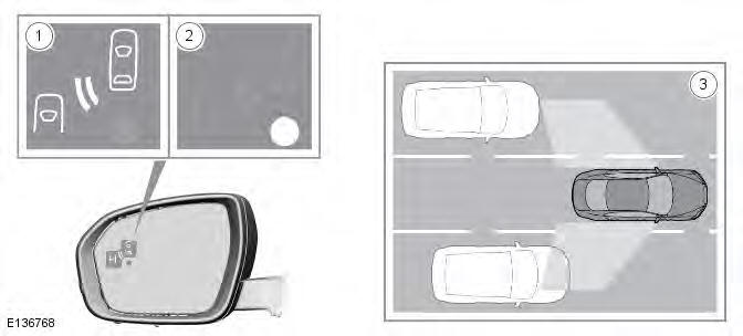
- Amber warning indicator icon
- Illuminated warning status indicator dot
- Not easily visible area
The Blind Spot Monitor (BSM) system monitors a zone that covers the area adjacent to the vehicle that is not easily visible by the driver and is designed to identify any object overtaking the vehicle (3). The system uses radars on each side of the vehicle to identify any overtaking vehicle/object within the blind spot area of the vehicle, while disregarding other objects which may be stationary or travelling in the opposite direction, etc.
If an object is identified by the system as being an overtaking vehicle/object, an amber warning indicator icon (1) illuminates in the relevant exterior mirror, to alert the driver that there is a potential hazard in the vehicle's blind spot and therefore, that a lane change might be dangerous.
NOTES:
This radar sensor is approved in all RTTE countries.
The system covers an area of a fixed lane width. If the lanes are narrower than a typical carriageway lane, objects travelling in non-adjacent lanes may be detected.
The amber warning indicator dot (2) remains illuminated until forward vehicle speed exceeds 16km/h (10mph).
BSM is designed to work most effectively when driving on multi-lane highways.
NOTES:
If an overtaking vehicle is detected on both sides of the vehicle simultaneously, the warning icons in both mirrors will illuminate.
BSM is automatically turned off when reverse (R) gear is selected, when the vehicle is in park (P), the vehicle is travelling below 10km/h (6mph). Under these conditions, the warning indicator dot in the exterior mirrors is displayed.
Component Description
The LED (light emitting diode) lighting sequence
The LED lighting sequence is as follows:
- Amber alert LED icon permanently lit - system operational, vehicle detected in blind spot area
- No LED is lit - system active no vehicle detected in blind spot area
- Amber status LED permanently lit - system not active or faulty
The system operating limitations
The system has operating limitations and is automatically turned off under certain operating conditions. During these operating conditions the amber status LED's permanently lit.
The system operating limitations are as follows:
- The area surrounding the radar face of the module must be clear of metallic items
- The system is inactive until vehicle speed is greater than 16km/h - 10mph (amber status LED permanently lit)
- The system is inactive if an approved trailer is connected to the vehicle (amber status LED permanently lit)
- The system is inactive when reverse gear or park is selected (amber status LED permanently lit)
If either of the radar signals is distorted by water, or if the radar face of the module is covered in mud, sleet or snow, the system may detect this and be disabled with the amber status LED permanently lit together with a 'blind spot monitoring blocked' message displayed in the instrument cluster message center. The system is disabled until the blockage is cleared.
If there is a fault in the system the amber status, LED is permanently lit and a 'blind spot monitoring not available' message displayed in the instrument cluster message center. The system is disabled until the fault is rectified.
System fault and blockage warnings
System fault and blockage warnings are as follows:
- The system is disabled when the radar module signal is blocked (amber status LED permanently lit and instrument cluster message)
- The system is disabled by a fault (amber status LED permanently lit and instrument cluster message)
If there is a failure in the communication network and the warning LED's cannot be displayed in the mirror, a failure message will be displayed in the instrument cluster message center.
When any faults are present in the system DTC (diagnostic trouble code)'s are stored in both blind spot monitoring modules appropriate to each module. Replacement of modules requires the right hand module to be configured using the Land Rover approved diagnostic equipment. Due to the fact that all modules are supplied as left hand modules, the replacement left hand modules do not require configuring.
Calibration of the modules using the Land Rover approved diagnostic equipment enables updates to be downloaded as new technology becomes available or any fault concerns require software updates.
Warning Devices
Torque Specifications

Principles of Operation
For a detailed description of the Blindspot Monitoring system, refer to the relevant Description and Operation sections in the workshop manual. REFER to: (413-09 Warning Devices)
Inspection and Verification
CAUTION: Diagnosis by substitution from a donor vehicle is NOT acceptable. Substitution of control modules does not guarantee confirmation of a fault, and may also cause additional faults in the vehicle being tested and/or the donor vehicle.
1. Verify the customer concern.
2. Visually inspect for obvious signs of damage and system integrity.
NOTE: Particular attention should be paid to the following items where DTCs may not be logged:
- Check for contamination (e.g. dirt, grime, frosting, ice) around the blindspot monitoring sensors and clear.
Visual Inspection
3. If an obvious cause for an observed or reported concern is found, correct the cause (if possible) before proceeding to the next step.
4. If the cause is not visually evident, verify the symptom and refer to the Symptom Chart, alternatively, check for Diagnostic Trouble Codes (DTCs) and refer to the DTC Index.
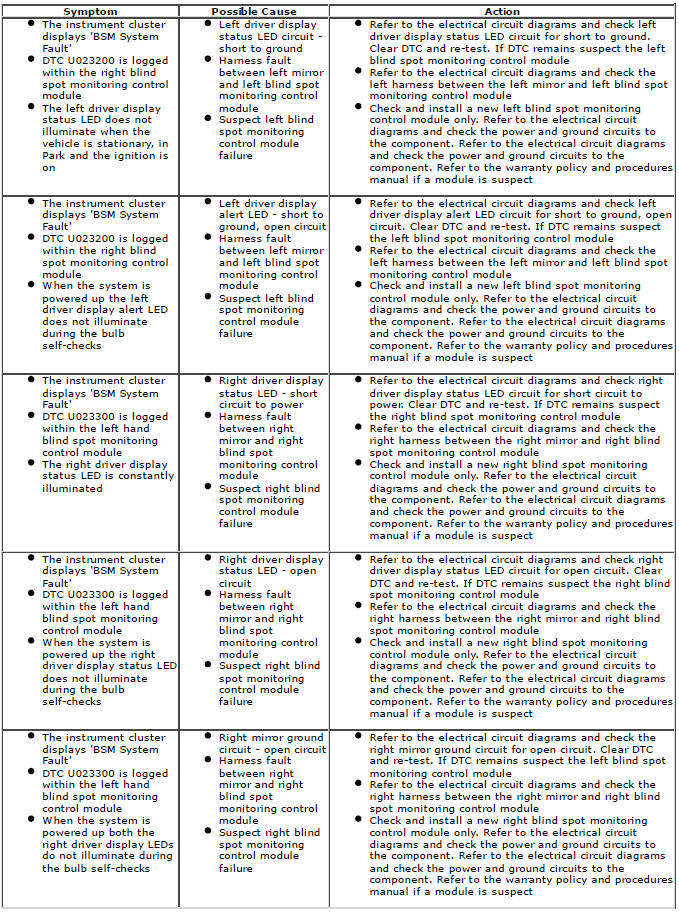
Symptom Chart

DTC Index
For a complete list of all Diagnostic Trouble Codes (DTCs) that could be logged on this vehicle, please refer to Section 100-00.
Service Indicator Reset
Synchronization
1. Set the ignition to the ON position.
2. Press the OK button on the right side of the steering wheel controls to access the Instrument cluster Main Menu.
3. Press the directional buttons to select the Service Menu.
4. Press the directional buttons to select the last option in the Menu.
5. Press and hold the trip button.
6. Press and hold the down directional button.
7. Hold both buttons for 10 seconds, this will reset the service indicator message.
8. Set the ignition to the OFF position.
9. Set the ignition to the ON position and check the message has been cleared.
10. If the message remains, repeat the process.
READ NEXT:
 Parking Aid - Component Location
NOTE: Park assist is not available to all markets.
COMPONENT LOCATION - SHEET 1 OF 4 - PARKING AID AND PARK ASSIST
TCM (transmission control module)
CJB (central junction box)
Touch Screen Displa
Parking Aid - Overview
OVERVIEW
The parking aid system provides an audible warning to the driver when any
obstacles are in the path of the vehicle during
forward or reverse parking maneuvers. The system consists of four ul
SEE MORE:
Important information
The information contained in this handbook covers all vehicle derivatives and
optional equipment,
some of which may not be fitted to your vehicle. Due to printing cycles, this
handbook may include
descriptions of options before they become generally available.
The vehicle options, hardware an
Symbols used in this handbook
Safety warnings indicate either a procedure which must be followed
precisely, or
information that should be considered with great care, in order to avoid the
possibility
of personal injury.
Cautions indicate either a procedure which must be followed precisely, or
information that
should
