Range Rover Evoque: Transmission Control Module (TCM), Gear Shift Module (GSM)
TRANSMISSION CONTROL MODULE (TCM)

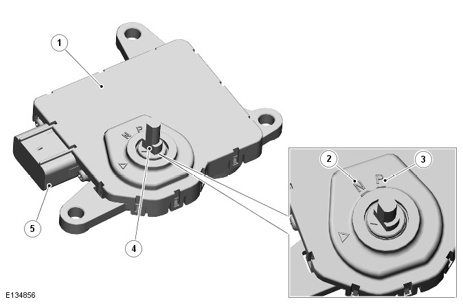
- TCM
- Neutral 'N' position
- Park 'P' position
- Position sensor/manual shaft
- Electrical connector
The TCM is located on the top of the transmission casing and is connected on the high speed CAN (controller area network) bus to send and receive information to and from other system modules.
The TCM outputs signals to operate the transmission solenoid valves to control the hydraulic operation of the transmission.
The ECM supplies the engine management data on the high speed CAN bus system. The TCM requires engine data to efficiently control the transmission operation, using for example; crankshaft torque, engine speed, accelerator pedal angle, engine temperature etc.
The TCM processes signals from the transmission speed and temperature sensors, ECM and other vehicle systems. From the received signal inputs and pre-programmed data, the TCM calculates the correct gear, torque converter clutch setting and optimum pressure settings for gear shift and lock-up clutch control.
The steering angle sensor and the ABS (anti-lock brake system) module also supply data to the TCM on the high speed CAN bus system. The TCM uses data from these systems to suspend gear changes when the vehicle is cornering and/or the ABS module is controlling braking or traction control.
The TCM is positioned over the transmission selector shaft which protrudes through an oil seal on the top face of the main transmission casing. The shaft locates in a rotary position sensor and turns the sensor in the appropriate direction. The Gear Shift Module (GSM), located above the TCM, rotates the shaft when a selection is made by the driver using the rotary TCS. The rotary position sensor is a Hall effect sensor which outputs a specified voltage relating to the selected TCS position.
The transmission is controlled by a 'shift by wire' system. The TCS is connected to the TCM and the GSM on the high speed CAN bus. Driver selections made on the TCS are passed via CAN messages to the GSM and the TCM. The GSM contains a rotary actuator which responds to driver selections and rotates the selector shaft in the appropriate direction.
If the TCM, GSM or transmission requires replacement, a setting procedure must be performed using a Land Rover approved diagnostic system to allow the TCM to learn the neutral position of the transmission. The TCM uses the neutral position as a reference point for each of the gear positions P, R, N, and D.
GEAR SHIFT MODULE (GSM)

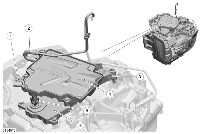
- Electrical connector
- Breather tube
- Mounting bracket
- Gear shift module
- Selector shaft extension
- Transmission control module
The GSM is mounted on a bracket on the top of the transmission, above the TCM. The GSM Is secured to the bracket with four bolts.
The GSM contains an integrated actuator which automatically controls the transmission gear selection in response to the 'gear selection' signal transmitted from the TCS. The GSM selects the requested gear based on all external parameter conditions being correct. The actuator drives a small connecting shaft which is located on top of the transmission selector shaft (above the TCM).
The GSM transmits a signal to inform the driver of the selected gear, illuminating the TCSLED (light emitting diode) 'PRNDS' and the instrument cluster displays. The gear position display in the instrument cluster has two modes; one mode displays P, R, N, D or S and the second mode displays the manual gear 1, 2, 3, 4, 5 or 6 when using the Land Rover CommandShift feature. The GSM monitors the TCS position, TCM engaged gear, lock status and the GSM actuator position to control the displays.
Emergency Park Engagement
The GSM has an emergency park engagement feature to place the transmission into 'Park' in the event of a system fault.
This function provides an external power input from the auxiliary battery module to the GSM, operating a motor which in turn rotates a cam which releases a spring loaded mechanism, placing the transmission into 'Park'.
Park Lock Control Strategy
The GSM controls the park lock function via CAN messages to the TCS.
The park lock control strategy is processed by the GSM. Park lock is activated when the TCS is in Park unless the brake pedal is pressed and the engine is running.
Alternatively if the engine is running and the TCS is placed in Park while the vehicle speed is too high, the TCS remains unlocked. When the speed decreases below a set threshold or the engine is switched off, the TCS Park lock function is activated.
A brake pedal status signal is received by the GSM on the CAN bus from the ECM. If the ECM signal is not available the ABS module provides back up information.
The GSM activates the Park lock when in Neutral unless the brake pedal is pressed. The lock request is ignored if the vehicle speed is greater than 6mph (10kph). When Neutral is selected, the lock is not activated for 2 seconds. This function allows the driver to move the TCS from R to D without the possibility of the Park lock being activated.
Manufacturing Mode
A new GSM is delivered in manufacturing mode. The module will function normally except Park selection is prevented.
In service, when replacing the GSM, the new module is supplied with manufacturing mode activated. The new module is programmed to the vehicle using a Land Rover Approved diagnostic system. Manufacturing mode is de-activated after the programming application learn process is complete.
Auxiliary Battery Module

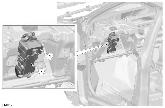
- Module
- Battery
The auxiliary battery module is a back up power supply system which supports automatic transmission Park selection, in the event of a system failure, by controlling the emergency park engagement feature of the GSM.
The auxiliary battery module system consists of a reserve battery and a module. The module has the following primary functions:
- Determine when to deploy the emergency park engagement function
- Provide the input signal to the GSM to activate the emergency park engagement system
- Provide emergency power and communication to the TCM during an emergency park engagement event
- Reserve battery charging.
The auxiliary battery module manages the reserve battery charging process, keeping the voltage charge level within a narrow window. The charging strategy is designed to extend the reserve battery service life (approximately four years).
During a vehicle power interruption the auxiliary battery module supplies emergency power to the TCM maintaining a primary line of communication via the LIN (local interconnect network) bus. This function provides the auxiliary battery module with information to determine the selected gear of the vehicle transmission.
The auxiliary battery module activates the emergency park engagement feature in the event that the GSM is unable to select Park.
The emergency park engagement function activates under the following conditions:
- A mechanical problem within the primary drive in the GSM exists
- The power supply to the GSM is interrupted
- Power supply to the TCS is interrupted and the driver is unable to select Park
The auxiliary battery module monitors the following primary input signals to determine if emergency park engagement should be triggered:
- Power mode
- Vehicle speed
- Gear position
The input signals are transmitted on the high speed CAN network to the TCM which processes and sends the data to the auxiliary battery module via the LIN bus. If a fault exists on the LIN bus the auxiliary battery module uses the vehicle battery voltage as a trigger for emergency park engagement activation.
If the vehicle battery voltage drops below 10.5V, and the LIN communication is lost or corrupt, the auxiliary battery module activates the emergency park engagement function.
Diagnostics
GSM failure will primarily result in the system inability to perform gear shifts between the PRND positions. It will not be possible to complete the position learning process correctly. This will be reflected to the driver by either no LED activity or flashing of the PRND illumination position depending on the position in which the system has failed. The TCS may be locked to prevent the driver from attempting further shifts in the failure condition.
TCS failure will result in no LED activity of the PRND illumination position, refusal of the TCS to rise, or the TCS rising when the conditions are not correct. The TCS may become locked in any position.
Auxiliary battery module failure can result in a loss of LIN communication with the TCM and automatic selection of the emergency park engagement system.
All failure modes, which result in a loss of functionality, will cause a "Gearbox Fault" warning being displayed in the instrument cluster
Emergency Park Release (Service Mode)
There is no mechanical provision to remove the vehicle from Park in the event of a system fault. However, a service mode is available which allows the TCS to rise without the engine running in order to permit Neutral selection in fault conditions.
The following procedure places the system into service mode:
- Hold the '+' gear shift paddle and depress the brake pedal continually for 10 seconds after the ignition has been switched on
- The system will remain in service mode until the ignition is switched off or the engine is started
NOTE: If there is a system power failure and the service mode function cannot be activated the only option available to remove the vehicle from Park is to remove the GSM unit from the vehicle. Once the GSM is removed the selector shaft can be manually rotated to the Neutral position. Refer to the relevant service repair procedure for access details.
CAUTION: Before the vehicle is driven and returned to the customer, the GSM gear position learning process must be completed using a Land Rover Approved diagnostic system. This MUST be completed any time the GSM is removed or replaced to ensure that position selection accuracy is maintained. Premature wear to the transmission or failure to select Park may result if the learning process is not performed.
INSTRUMENT CLUSTER
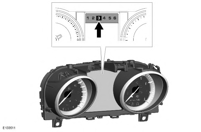
NOTE: The following illustration shows the display when the transmission is in CommandShift mode. PRNDS is displayed during normal transmission operation.

The instrument cluster is connected to the TCM via the high speed CAN. Transmission status is transmitted by the TCM and displayed to the driver in the instrument cluster.
Malfunction Indicator Lamp (MIL)
The MIL (malfunction indicator lamp) is located in the upper LH corner of the instrument cluster, within the tachometer.
Transmission related faults which may affect the vehicle emissions output will illuminate the MIL.
TheMIL is illuminated by the ECM on receipt of a relevant fault message from the TCM on the CAN. The nature of the fault can be diagnosed using a Land Rover approved diagnostic system which reads fault codes stored in the memory.
Transmission Status Display
The transmission status display is located in the central LCD (liquid crystal display) message display in the instrument cluster. The display shows the selected P R N D S position and in the case of manual 'CommandShift' mode, the selected gear.

