Range Rover Evoque: Transmission Description - System Operation and Component Description
Control Diagram
NOTE: A = Hardwired; D = High Speed Controller Area Network (CAN) bus; O = Local Interconnect Network ( LIN)
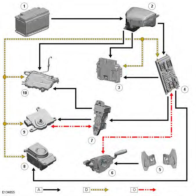
- Battery
- Battery Junction Box (BJB)
- Engine Control Module (ECM)
- Central Junction Box (CJB)
- Transmission paddle switches
- Clockspring
- Auxiliary battery module
- Transmission Control Switch (TCS)
- Transmission Control Module (TCM)
- Gear Shift Module (GSM)
System Operation
OPERATION
Operation of the transmission is controlled by the TCM (transmission control module), which electrically activates various solenoids to control the transmission gear selection. The sequence of solenoid activation is based on programmed information in the TCM memory and physical transmission operating conditions such as vehicle speed, throttle position, engine load and rotary TCS (transmission control switch) position.
Engine torque is transferred, via operation of single or combinations of clutches to the planetary gear trains. The gear trains are controlled by reactionary inputs from brake clutches to produce the 6 forward gears and 1 reverse gear.
The shift elements (clutches and brakes) are actuated hydraulically. Fluid pressure is applied to the required clutch and/or brake, pressing the plates together and allowing drive to be transmitted through the plates. The purpose of the shift elements is to perform power-on shifts with no interruption to traction and smooth transition between gear ratios.
Component Description
DESCRIPTION
The transmission comprises the main casing which houses all of the transmission components. The torque converter is located in a separate converter housing.
AW F21 Automatic Transmission - Sectional View
- Clutch - C2
- Brake - B2
- One-way clutch - F1
- Clutch - C1
- Brake - B1
- Clutch - C3
- Torque converter
- Fluid pump
- Differential assembly
- Counter driven gear
- Counter drive gear
The main casing retains the fluid at the bottom. A combined drain/level plug is located in the bottom of the casing. The oil level is checked by removal of the inner level plug, with the engine running and the transmission fluid at a temperature of between 50 to 60
- Torque Converter, Valve Block
- Drive Clutches, Planetary Gear Train
- Power Flows
- Transmission Control Module (TCM), Gear Shift Module (GSM)
- Driving Modes
READ NEXT:
 Torque Converter, Valve Block
TORQUE CONVERTER
Torque converter housing
Lock-up clutch
Turbine
Impeller
Stator
Fluid pump
Input shaft
The torque converter is the coupling element between the engine and the
transmission
Drive Clutches, Planetary Gear Train
DRIVE CLUTCHES
Multiplate Drive or Brake Clutch - Typical
Input shaft
Main pressure supply port
Piston
Cylinder - External plate carrier
Clutch plate assembly
Baffle plate
Diaphragm spring
O
Power Flows
Operation of the transmission is controlled by the TCM which electrically
activates various solenoids to control the
transmission gear selection. The sequence of solenoid activation is based on
prog
SEE MORE:
Communications Network - Overview, System
Operation and Component Description
Overview
A number of different types of communication networks are incorporated into
the vehicle wiring harnesses for the
transmission of commands and information between control modules. The
configuration installed on a particular vehicle
depends on the model and equipment level.
The communicati
Communications Network - Diagnosis and Testing
Principles of Operation
For a detailed description of the Communications Network, refer to the
relevant Description and Operation sections in the
workshop manual.
Inspection and Verification
CAUTIONS:
Diagnosis by substitution from a donor vehicle is NOT acceptable.
Substitution of control modules
