Range Rover Evoque: Torque Converter, Valve Block
TORQUE CONVERTER

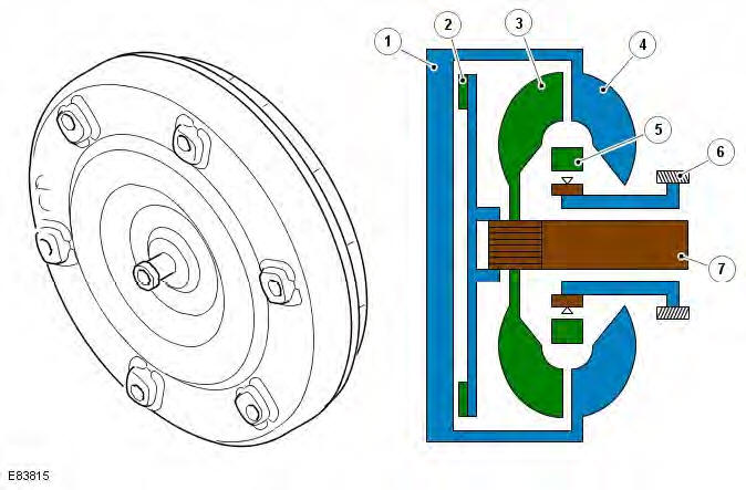
- Torque converter housing
- Lock-up clutch
- Turbine
- Impeller
- Stator
- Fluid pump
- Input shaft
The torque converter is the coupling element between the engine and the transmission and is located in the transmission housing, on the engine side of the transmission. The driven power from the engine crankshaft is transmitted hydraulically and mechanically through the torque converter to the transmission. The torque converter is connected to the engine by a drive plate.
The torque converter comprises an impeller, a stator and a turbine. The torque converter is a sealed unit with all components located between the converter housing cover and the impeller. The two components are welded together to form a sealed, fluid filled housing. With the impeller welded to the converter housing cover, the impeller is therefore driven at engine crankshaft speed.
The torque converter contains a hydraulically operated lock-up clutch which is controlled by the TCM via a solenoid in the valve block which actuates spool valves to control the hydraulic pressure applied to the clutch. This allows the TCM to provide 3 modes of converter operation; unlocked, partially locked and fully locked.
VALVE BLOCK
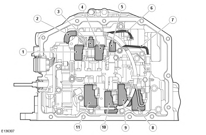
The valve block is located in a vertical position at the front of the transmission main casing, behind a sealed cover. The valve block contains a number of solenoids, dampers and spool valves to control the transmission operation. The solenoids are controlled by the TCM to provide gear changes and smooth transition between ratio changes.

- Lock-up control solenoid - SLU
- Transmission harness
- 3-Way solenoid - S2
- Line pressure control solenoid - SLT
- 3-Way solenoid - S1
- Input speed sensor wires
- Output speed sensor wires
- Shift control solenoid - SLB1
- Shift control solenoid - SLC3
- Shift control solenoid - SLC2
- Shift control solenoid - SLC1
Shift Control Solenoids - SLC1, SLC2, SLC3, SLB1
The shift control solenoids (SLC1, SLC2, SLC3 and SLB1) are installed on the front valve body. The solenoids respond to inputs from the TCM and control the hydraulic pressure applied to the clutches (C1, C2 and C3) and to the brake B1 to provide smooth shifting. The TCM uses a single or a combination of these solenoids to provide shifts from 1st to 6th gear.
If a solenoid fails, the TCM will remove the current to the shift control solenoids and the transmission will use limp home mode, to prevent damage to the transmission.
Line Pressure Control Solenoid - SLT
The line pressure control solenoid (SLT) is installed on the front valve body. The solenoid is controlled in a linear manner by the TCM which uses throttle opening degree signals and engine torque information from the ECM (engine control module) to determine the solenoid operation. The solenoid controls the line pressure applied to the clutches and brakes to provide smooth shifting.
If the solenoid fails, the TCM will remove the current supplied to the solenoid. Maximum line pressure will be applied to the clutches and brakes unless the failure is due to the solenoid valve sticking, which may result in low line pressure.
Lock-Up Control Solenoid - SLU
The lock-up control solenoid is installed on the front valve body. The solenoid is controlled in a linear manner by the TCM which uses engine speed, throttle opening degree signals and transmission speed sensor signals to determine the solenoid operation. The solenoid controls the amount of lock-up or slip required for the torque converter lock-up clutch.
If the solenoid fails, the TCM removes the current supplied to the solenoid which results in no torque converter lock-up being applied.
3-Way Solenoid - S1, S2
The 3-way solenoid (S1) is located on the center valve body and solenoid (S2) is located on the front valve body. The solenoids are on/off solenoids controlled by the TCM. A combination of the 2 solenoids is used to operate either the 1st gear engine braking or enable gear shifts.
If a solenoid fails, the TCM will remove the current supplied to both solenoids.
Speed Sensors

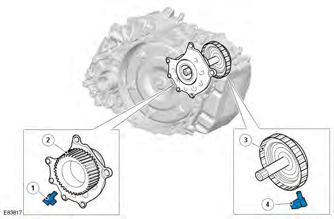
- Speed Sensor (SP) - Output shaft speed
- Counter drive gear
- C2 clutch drum
- Speed sensor (NIN)
Two speed sensors (NIN and SP) are used in the transmission and are located within the transmission housing. Speed sensor (SP) is located adjacent to the counter drive gear and reads from the gear teeth to provide an output shaft speed signal. Speed sensor (NIN) is located adjacent to the clutch C" drum and reads off teeth on the outer circumference of the drum to provide an input shaft speed. Both speed signals are received by the TCM which uses the 2 signals to calculate engine torque output, shift timing and torque converter lock-up.
Fluid Temperature Sensor
The fluid temperature sensor is integrated into the internal wiring harness within the transmission. It detects the fluid temperature in the hydraulic pressure control circuit and transmits a signal corresponding to the temperature to the TCM.
The TCM monitors the temperature and provides smooth gear shifts across a wide range of temperatures.

