Range Rover Evoque: Multifunction Electronic Modules
Torque Specifications

Front Door Module (FDM)
Removal
NOTE: Removal steps in this procedure may contain installation details.
1. Disconnect the battery ground cable.
Refer to: Specifications (414-01 Battery, Mounting and Cables, Specifications).
2. Refer to: Front Door Trim Panel (501-05 Interior Trim and Ornamentation, Removal and Installation).
3. NOTE: Left-hand shown, right-hand similar.
Installation
1. CAUTION: If a new component has been installed, configure using Land Rover approved diagnostic equipment. To install, reverse the removal procedure.
Rear Door Module (RDM)
Removal
NOTE: Removal steps in this procedure may contain installation details.
1. Disconnect the battery ground cable.
Refer to: Specifications (414-01 Battery, Mounting and Cables, Specifications).
2. Refer to: Rear Door Trim Panel (501-05 Interior Trim and Ornamentation, Removal and Installation).
3. NOTE: Left-hand shown, right-hand similar.
Installation
1. CAUTION: If a new component has been installed, configure using Land Rover approved diagnostic equipment. To install, reverse the removal procedure.
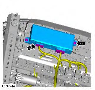
Driver Seat Module (DSM)
Removal
NOTE: Removal steps in this procedure may contain installation details.
1. Disconnect the battery ground cable.
Refer to: Specifications (414-01 Battery, Mounting and Cables, Specifications).
2. WARNING: To avoid accidental deployment, the restraints control module backup power supply must be depleted. Wait at least two minutes after disconnecting the battery ground cable(s) before commencing any repair or adjustment to the supplemental restraint system (SRS), or any component(s) adjacent to the SRS sensors.
Failure to follow these instructions may result in personal injury.
Make the SRS system safe.
Refer to: Standard Workshop Practices (100-00 General Information, Description and Operation).
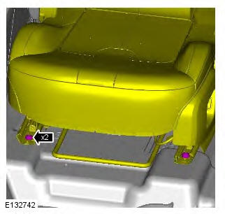
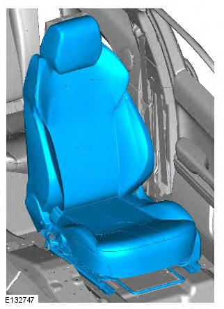
3. CAUTION: Make sure that new bolts are installed.
Torque: 40 Nm
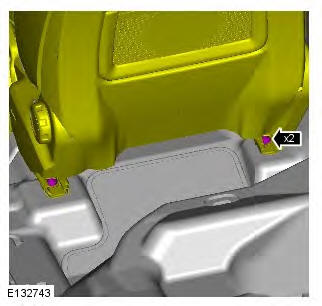
4. CAUTION: Make sure that new bolts are installed.
Torque: 40 Nm
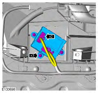
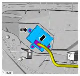
5.
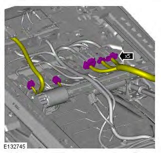
6. CAUTIONS: Protect the surrounding paintwork to avoid damage.
Care must be taken to avoid damaging the surrounding components.
7. Torque: 2.5 Nm
Installation
1. To install, reverse the removal procedure.
2. If a new component has been installed, configure using Land Rover approved diagnostic equipment.
Module Controlled Functions - Component Location
COMPONENT LOCATION - LIN BUS (SHEET 1 OF 2)
- CJB (central junction box)
- Immobilizer Antenna Unit (IAU)
- Cabin humidity sensor
- Rain sensor
- Front overhead console
- Roof blind motor
- Passenger heated seat module
- Driver heated seat module
- Clockspring
- Integrated Control Panel (ICP)
- Battery backed sounder (if fitted)
- Battery Monitoring System (BMS) module
- Heater core and evaporator core housing
- Voltage quality module
- LH (left-hand) air temperature mode motor
- Face/feet mode air distribution motor
- RH (right-hand) air temperature mode motor
- Screen air distribution motor
- Fresh/recirculated mode motor
COMPONENT LOCATION - LIN BUS (SHEET 2 OF 2)
- Headlamp control module
- ECM (engine control module)
- Driver mirror window switch pack
- RH front door module
- Radio Frequency (RF) receiver
- RH rear door module
- Keyless Vehicle Module (KVM)
- LH rear door module
- LH front door module
- Auxiliary battery module
- TCM (transmission control module)
- LH headlamp
- Generator
- RH headlamp
COMPONENT LOCATION - MEDIUM SPEED CAN BUS - SHEET 1 OF 2
- Touch Screen Display (TSD)
- Integrated Control Panel (ICP)
- Fuel Fired Booster Heater (FFBH)
- RH front door module
- Interior mirror
- LH front door module
- Diagnostic socket
- Instrument cluster
- Driver seat memory module
- Proximity camera control module
- Passenger seat memory module
- CJB
COMPONENT LOCATION - MEDIUM SPEED CAN BUS - SHEET 2 OF 2
- Navigation system module (Asia)
- RH blindspot monitoring module
- Rear view camera
- Liftgate module
- LH blindspot monitoring module
- Keyless Vehicle Module (KVM)
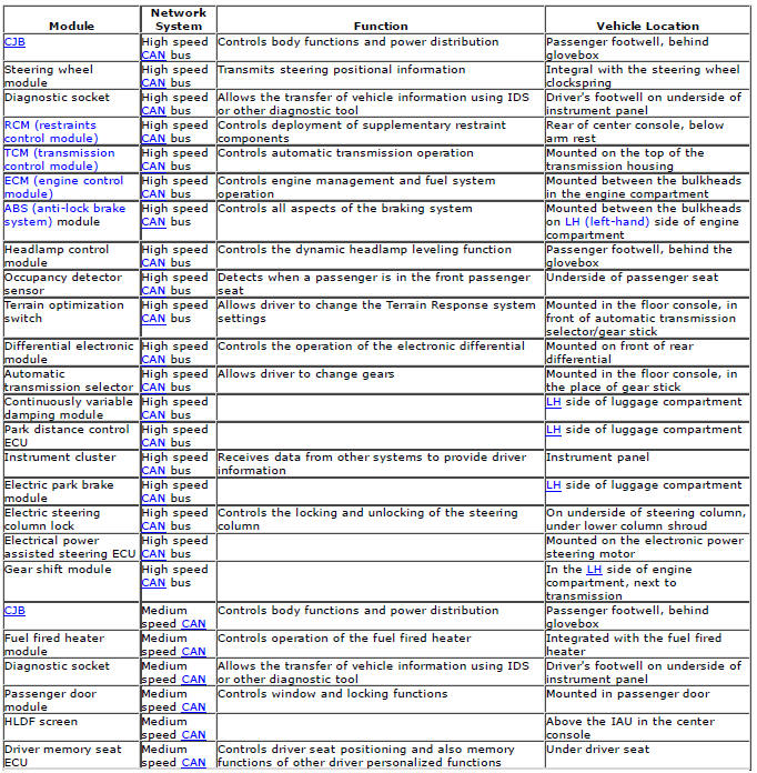
COMPONENT LOCATION - HIGH SPEED CAN BUS
- CJB
- Headlamp control module
- ECM
- Occupancy detector sensor
- Electronic Transmission Selector (ETS)
- Terrain optimization switch
- Instrument cluster
- RCM (restraints control module)
- Differential electronic module
- Park distance control module
- Electric park brake module
- Continuously variable damping module
- Electric steering column lock
- Clockspring
- ABS (anti-lock brake system) module
- TCM
- Diagnostic socket
- Gear shift module
- Electric power assisted steering rack
COMPONENT LOCATION - MOST
- Integrated Audio Module (IAM)
- Touch Screen Display (TSD)
- Rear Seat Entertainment (RSE) module
- Satellite Digital Audio Radio Service (SDARS) module (NAS Only) or Digital Audio Broadcasting (DAB) module
- TV Module
- Audio power amplifier
- Diagnostic socket
Module Controlled Functions - Overview
OVERVIEW
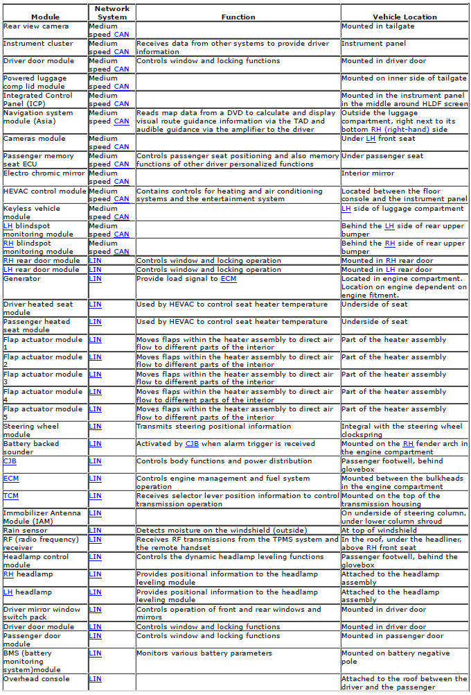
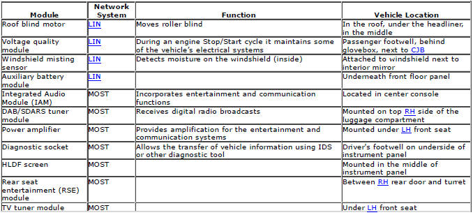
The vehicle electrical system comprises a number of control modules which are interconnected via several network systems.
The following network systems are used on the vehicle:
- High Speed Controller Area Network bus
- Medium speed CAN (controller area network) bus
- LIN (local interconnect network) bus
- Media Orientated Systems Transport (MOST) system.
The CJB (central junction box) is the 'gateway' for the network systems which allows information to be exchanged between networks.
The entertainment system components are connected on a fiber optic MOST system. The MOST system can send and receive information to/from the other network systems via a 'gateway' in the HLDF screen.
The following table shows each vehicle control module, the network system to which it is connected, its function and location in the vehicle.
Module Controlled Functions - System Operation and Component Description
Control Diagram
NOTE: For additional information, refer to Communications Network (418-00).
System Operation
Refer to: Module Controlled Functions (419-10 Multifunction Electronic Modules, Description and Operation).
Component Description
Component Description
Refer to: Module Controlled Functions (419-10 Multifunction Electronic Modules, Description and Operation).
Driver Door Module (DDM)
Description and Operation
For a detailed description of the multifunction electronic control modules, refer to the relevant description and operation sections in the workshop manual REFER to: (419-10 Multifunction Electronic Modules)
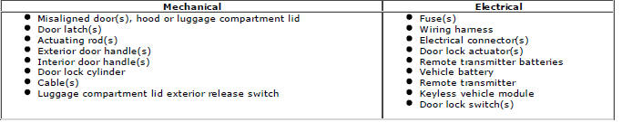
Inspection and Verification
CAUTION: Diagnosis by substitution from a donor vehicle is NOT acceptable. Substitution of control modules does not guarantee confirmation of a fault, and may also cause additional faults in the vehicle being tested and/or the donor vehicle
1. Verify the customer concern
2. Visually inspect for obvious signs of damage and system integrity
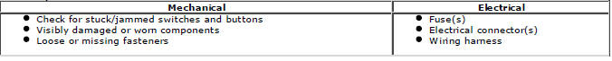
Visual Inspection

3. If an obvious cause for an observed or reported concern is found, correct the cause (if possible) before proceeding to the next step
4. If the cause is not visually evident, check for diagnostic trouble codes (DTCs) and refer to the diagnostic trouble codes index
DTC Index
For a list of diagnostic trouble codes that could be logged on this vehicle, please refer to Section 100-00.
Remote Keyless Entry (RKE) Module
Principles of Operation
For a detailed description of the keyless vehicle system, refer to the relevant description and operation sections in the workshop manual.
Inspection and Verification
CAUTION: Diagnosis by substitution from a donor vehicle is NOT acceptable. Substitution of control modules does not guarantee confirmation of a fault, and may also cause additional faults in the vehicle being tested and/or the donor vehicle.
1. Verify the customer concern
2. Visually inspect for obvious signs of damage and system integrity
Visual Inspection
3. If an obvious cause for an observed or reported concern is found, correct the cause (if possible) before proceeding to the next step
4. If the cause is not visually evident, check for diagnostic trouble codes (DTCs) and refer to the DTC index
DTC Index
For a list of diagnostic trouble codes that could be logged on this vehicle, please refer to Section 100-00.
REFER to: Diagnostic Trouble Code (DTC) Index - DTC: Keyless Vehicle Module (KVM) (100-00 General Information, Description and Operation).
Passenger Door Module (PDM)
Principles of Operation
For a detailed description of the passenger door module, refer to the relevant description and operation sections in the workshop manual. REFER to: (419-10 Multifunction Electronic Modules)
Inspection and Verification
CAUTION: Diagnosis by substitution from a donor vehicle is NOT acceptable. Substitution of control modules does not guarantee confirmation of a fault, and may also cause additional faults in the vehicle being tested and/or the donor vehicle
1. Verify the customer concern
2. Visually inspect for obvious signs of damage and system integrity
Visual Inspection
3. If an obvious cause for an observed or reported concern is found, correct the cause (if possible) before proceeding to the next step
4. If the cause is not visually evident, check for diagnostic trouble codes (DTCs) and refer to the diagnostic trouble codes index
DTC Index
For a list of diagnostic trouble codes that could be logged on this vehicle, please refer to Section 100-00.