Range Rover Evoque: Steering Linkage
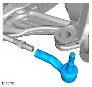
Tie Rod End
Special Tool(s)
 205-754A
Splitter, Ball Joints
Removal
NOTE: RH illustration shown, LH is similar.
1. WARNING: Make sure to support the vehicle with axle stands. Raise and support the vehicle.
2. Refer to: Wheel and Tire (204-04 Wheels and Tires, Removal and Installation).
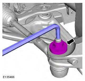
3.

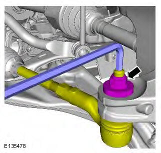
4. CAUTIONS:
Make sure that the ball joint ball does not rotate.
Discard the nut.
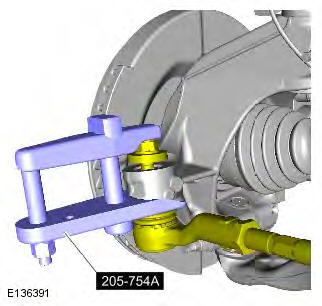
5. CAUTION: Make sure that the ball joint seal is not damaged. Special Tool(s): 205-754A
6.
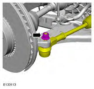
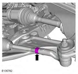
7. CAUTION: Note the number of turns when removing the tie rod end to aid installation.

Installation
1. CAUTION: Make sure that the tie rod end is installed with the same number of turns as when removed.
2. WARNING: Make sure that a new nut is installed.
CAUTION: Make sure that the ball joint ball does not rotate. Torque: 133 Nm
3. Torque: 100 Nm
4. Refer to: Wheel and Tire (204-04 Wheels and Tires, Removal and Installation).
5. Using only four wheel alignment equipment approved by Land Rover, check and adjust the wheel alignment.
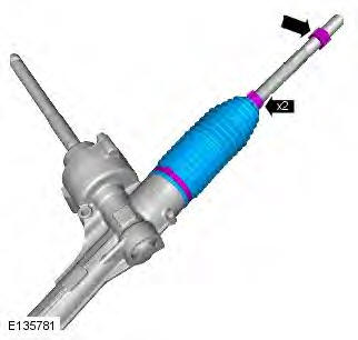
Steering Gear Boot
Removal
NOTE: LHD illustration shown, RHD is similar
1. WARNING: Make sure to support the vehicle with axle stands.
Raise and support the vehicle.
2. Refer to: Tie Rod End (211-03 Steering Linkage, Removal and Installation).
3. NOTES:
Note the position of the components prior to removal.
Discard the retaining clips.
Installation
1. NOTES:
Make sure that these components are installed to the noted removal position.
Install new retaining clips.

2. Refer to: Tie Rod End (211-03 Steering Linkage, Removal and Installation).
Steering Linkage
Torque Specifications

* New nut must be installed
READ NEXT:
 Steering Column
Steering Column - Component Location
Upper column
Steering wheel
Intermediate shaft
Steering Column - Overview
The steering column consists of an intermediate shaft, the upper column and
the st
Steering Column Switches
Torque Specifications
Steering Column Multifunction Switch
Removal
NOTES:
Removal steps in this procedure may contain installation details.
Removal of the windshield wiper switch assembly is identic
SEE MORE:
Important information
The information contained in this handbook covers all vehicle derivatives and
optional equipment,
some of which may not be fitted to your vehicle. Due to printing cycles, this
handbook may include
descriptions of options before they become generally available.
The vehicle options, hardware an
Symbols used in this handbook
Safety warnings indicate either a procedure which must be followed
precisely, or
information that should be considered with great care, in order to avoid the
possibility
of personal injury.
Cautions indicate either a procedure which must be followed precisely, or
information that
should
