Range Rover Evoque: Steering Column
Steering Column - Component Location
- Upper column
- Steering wheel
- Intermediate shaft
Steering Column - Overview
The steering column consists of an intermediate shaft, the upper column and the steering wheel, which are connected together to transfer driver steering inputs to the steering gear.
The steering column incorporates rake and reach adjustment, an electric steering column lock (all except NAS (North American Specification) ) and a steering column collapse actuator (NAS only). Some vehicles also incorporate a steering wheel heater. Multifunction switches are attached to the steering wheel module on the upper column and to the steering wheel, for operation of the following vehicle systems:
- Exterior lighting.
Refer to: Exterior Lighting (417-01 Exterior Lighting, Description and Operation).
- Wipers and washers.
Refer to: Wipers and Washers (501-16 Wipers and Washers, Description and Operation).
- Speed control.
- Steering wheel heater.
- Audio/Video.
Refer to: Audio System (415-01 Information and Entertainment System, Description and Operation).
- Vehicle information and settings menu.
- Refer to: Information and Message Center (413-08 Information and Message Center, Description and Operation).
- Telephone and voice control. Refer to 419-08.
The steering wheel also incorporates the driver air bag, with integrated horn switch.
Refer to: Air Bag Supplemental Restraint System (SRS) (501-20B Supplemental Restraint System, Description and Operation).
On automatic transmission vehicles, two paddle switches are attached to the steering wheel.
Refer to: External Controls (307-05 Automatic Transmission/Transaxle External Controls - Vehicles With: AWF21 6-Speed Automatic Transmission, Description and Operation).
Steering Column - System Operation and Component Description
Control Diagram
NOTE: A = Hardwired connection.
- Battery
- EJB (engine junction box)
- Clockspring
- Heater mat and temperature sensor
- Heated steering wheel module
- Heated steering wheel switch
System Operation
STEERING WHEEL HEATER (WHERE FITTED)
The heated steering wheel module receives a power supply from the extended ignition relay in the EJB via the clockspring.
When the driver operates the heated steering wheel switch, a path is completed between the switch and the heated steering wheel module, which then supplies power to the heater mat. The heated steering wheel module monitors the heater mat temperature using the temperature sensor, and controls the power supply to keep the heater mat at the optimum temperature.
Component Description
INTERMEDIATE SHAFT
- Outer tube
- Upper universal joint
- Inner tube
- Lower universal joint
The intermediate shaft consists of inner and outer steel tubes that can collapse telescopically to isolate the steering wheel from any movement of the steering gear during an impact. The tubes are bonded together with a stiff thin-walled elastomer to help isolate road noise. Universal couplings connect the ends of the intermediate shaft to the upper column and the input shaft of the steering gear.
UPPER COLUMN
- Steering column collapse actuator (NAS only)
- Upper shroud
- Screw (2 off)
- Switchgear assembly
- Lower shroud
- Screw (2 off)
- IAU transceiver (where fitted)
- Rake adjustment slot
- Upper column shaft
- Bearing housing
- Adjustment locking lever
- Reach adjustment slot
- Locking mechanism
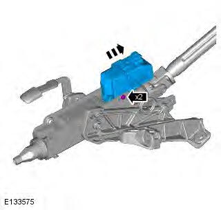
- Electric steering column lock
- Pivot pin
- Reach adjustment slots
- Outer bracket
- Energy management plate
- Inner bracket
The shaft of the upper column is installed in a bearing housing that is attached to an inner bracket with a pivot pin and an adjustment locking mechanism. Slots at the attachment points, in the bearing housing and the inner bracket, allow the bearing housing to move axially and to tilt in the inner bracket, to provide the rake and reach adjustment of the steering wheel. The locking mechanism is a friction lock, operated by a lever turning a cam disc.
The inner bracket is located on rails in an outer bracket, which is attached to the cross car beam. The inner and outer brackets are locked together by an energy management plate, which is attached to both brackets with screws. In a serious impact, to prevent excessive force causing injury as the driver strikes the air bag, the inner bracket progressively moves forwards on the rails in the outer bracket. The movement is controlled by the energy management plate. The plate has leaves attached to the inner bracket, which peel back in a controlled manner, absorbing energy and allowing the steering wheel to move with the driver.
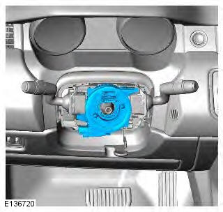
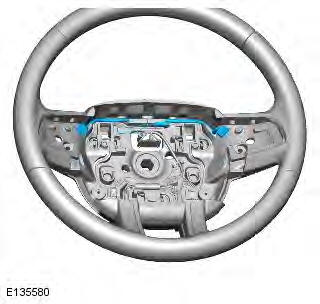
The steering wheel module is attached to the top of the upper column by two bolts. The module incorporates the clockspring and the multifunction switches for the exterior lighting and the windows and washers.
Upper and lower shrouds cover that part of the upper column not concealed by the instrument panel. On vehicles with passive entry passive start, an IAU (immobilizer antenna unit) transceiver is installed in the lower shroud.
Electric Steering Column Lock (All Except NAS)
An electric steering column lock is attached to the underside of the bearing housing. On NAS (North American Specification) vehicles, only the body of the lock is installed, to provide a forward attachment point for the steering column lower shroud (as well as the internal mechanism being removed, the lock has also been disabled in the car configuration files).
Refer to: Anti-Theft - Passive (419-01B Anti-Theft - Passive, Description and Operation).
Steering Column Collapse Actuator (NAS Only)
A steering column collapse actuator is installed to provide increased energy absorption to allow for a driver not wearing a safety belt. If the driver is wearing a safety belt and a crash situation occurs, the actuator is not activated.
The steering column collapse actuator is located below the energy management plate. A pin on the actuator is engaged in a hole in the central leaf of the energy management plate. When the driver safety belt is not fastened and a crash situation occurs which requires the driver air bag to be deployed, the RCM (restraints control module) activates the actuator, which retracts the pin from the central leaf in the energy management plate. This provides the required increase in energy absorption to allow for the additional loading caused by the unrestrained driver.
STEERING WHEEL
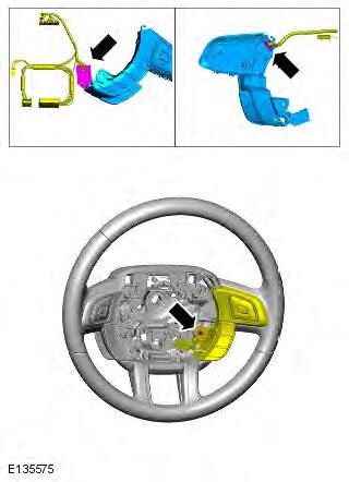
- Upshift paddle switch (automatic transmission only)
- RH (right-hand) multifunction switchpack
- Heated steering wheel module
- Driver air bag
- Steering wheel securing screw
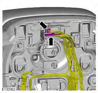
- Heater mat connector
- LH (left-hand) multifunction switchpack
- Downshift paddle switch (automatic transmission only)
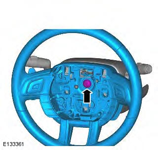
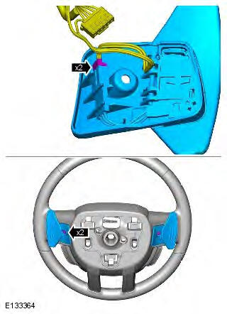
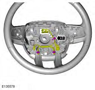
The steering wheel is located on the hexagonal drive end of the upper column shaft and secured with a M10 pan headed screw.
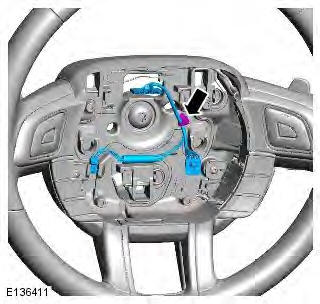
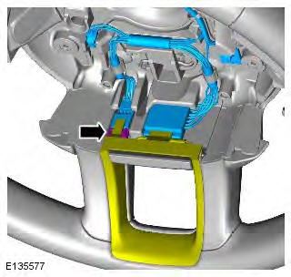
The driver air bag and two multifunction switchpacks are installed in the center of the steering wheel. On automatic transmission vehicles, upshift and downshift paddle switches are attached to the front of the steering wheel. A link harness connects the steering wheel components to the clockspring.
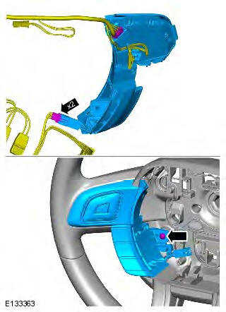
Steering Wheel Heater (Where Fitted)
The steering wheel heater consists of a heater mat and NTC (negative temperature coefficient) temperature sensor installed around the rim of the steering wheel under the trim. A heated steering wheel module, integrated into the link harness, regulates the temperature of the heater mat. A switch on the LH multifunction switchpack switches the heater on and off.
A heater symbol in the switch is illuminated amber when the steering wheel heater is on. When the steering wheel heater is off, the symbol is either not illuminated or, if the exterior lighting is on, illuminated green.
Steering Column
General Specification

Torque Specifications
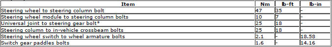
* New nuts/bolts must be fitted
Steering Wheel
Removal
CAUTION: Make sure that the road wheels are in the straight ahead position.
NOTE: Removal steps in this procedure may contain installation details.
1. Make the SRS system safe.
Refer to: Standard Workshop Practices (100-00 General Information, Description and Operation).
2. Refer to: Driver Air Bag Module (501-20B Supplemental Restraint System, Removal and Installation).
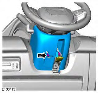
3.
4. Torque: 47 Nm
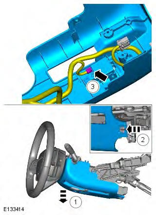
5. CAUTION: Make sure that the clockspring rotor does not rotate. Secure with adhesive tape.
6. NOTE: Do not disassemble further if the component is removed for access only. Torque: 1.6 Nm
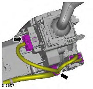
7. CAUTION: Take extra care not to damage the edges of the component. Torque: 2.1 Nm
8. CAUTION: Take extra care not to damage the edges of the component. Torque: 2.1 Nm
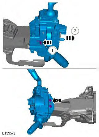
9.
10.
11. NOTE: Where fitted.
12. NOTE: Where fitted.
Installation
1. To install, reverse the removal procedure.
2. If a new component is installed, the soft lock stop reset routine should be completed on the power steering system, using the approved diagnostic tool.
Steering Column
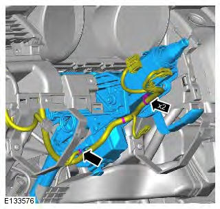
Removal
CAUTION: Make sure that the road wheels are in the straight ahead position.
NOTE: Removal steps in this procedure may contain installation details.
1. Make the SRS system safe.
Refer to: Standard Workshop Practices (100-00 General Information, Description and Operation).
2. Refer to: Steering Wheel (211-04 Steering Column, Removal and Installation).
3. Refer to: Driver Lower Air Bag Module (501-20B Supplemental Restraint System, Removal and Installation).
4.
5.
6.
7. Torque: 10 Nm
8.
9. CAUTION: Discard the bolt. Torque: 25 Nm
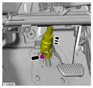
10. Torque: 25 Nm
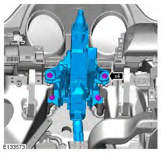
11. NOTE: Do not disassemble further if the component is removed for access only. Using a suitable stud extraction tool, remove the tamper proof bolts.
Installation
1. WARNING: Make sure that a new steering column flexible coupling bolt is installed.
CAUTION: Tighten the new tamper proof bolts until the hexagon shears. To install, reverse the removal procedure.
2. If a new component is installed, the soft lock stop reset routine should be completed on the power steering system, using the approved diagnostic tool.
Steering Column
Principle of Operation
For a detailed description of the Steering System and operation, refer to the relevant Description and Operation section of the workshop manual. REFER to: (211-04 Steering Column)
Inspection and Verification
CAUTIONS:
Diagnosis by substitution from a donor vehicle is NOT acceptable. Substitution of control modules does not guarantee confirmation of a fault, and may also cause additional faults in the vehicle being tested and/or the donor vehicle.
When probing connectors to take measurements in the course of the pinpoint tests, use the adapter kit, part number 3548-1358-00.
NOTES:
If the control module or a component is suspect and the vehicle remains under manufacturer warranty, refer to the Warranty Policy and Procedures manual (section B1.2), or determine if any prior approval programme is in operation, prior to the installation of a new module/component.
Generic scan tools may not read the codes listed, or may read only 5-digit codes. Match the 5 digits from the scan tool to the first 5 digits of the 7-digit code listed to identify the fault (the last 2 digits give extra information read by the manufacturer-approved diagnostic system).
When performing voltage or resistance tests, always use a digital multimeter accurate to three decimal places, and with an up-to-date calibration certificate. When testing resistance always take the resistance of the digital multimeter leads into account.
Check and rectify basic faults before beginning diagnostic routines involving pinpoint tests.
Inspect connectors for signs of water ingress, and pins for damage and/or corrosion.
If DTCs are recorded and, after performing the pinpoint tests, a fault is not present, an intermittent concern may be the cause. Always check for loose connections and corroded terminals.
1. Verify the customer concern
2. Visually inspect for obvious signs of damage and system integrity.
Visual Inspection
- Fuses
- Wiring harness
- Loose or corroded connector(s)
- Steering wheel heater switch
3. If an obvious cause for an observed or reported concern is found, correct the cause (if possible) before proceeding to the next step
4. If the cause is not visually evident, verify the symptom and refer to the Symptom Chart, alternatively check for Diagnostic Trouble Codes (DTCs) and refer to the DTC Index
5. Check DDW for open campaigns. Refer to the corresponding bulletins and SSMs which may be valid for the specific customer complaint and carry out the recommendations as required
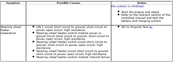
Symptom Chart

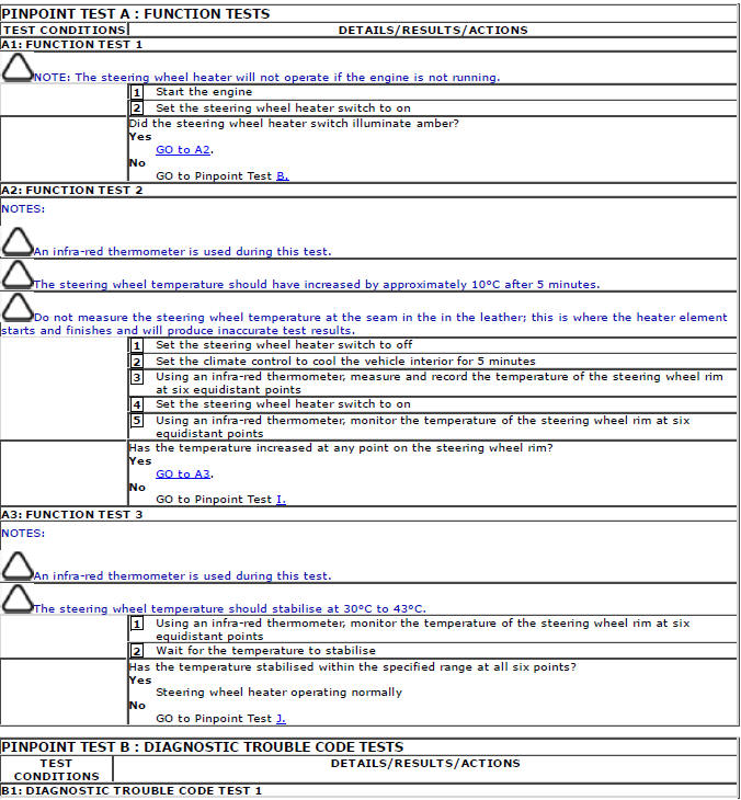
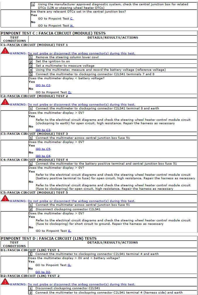
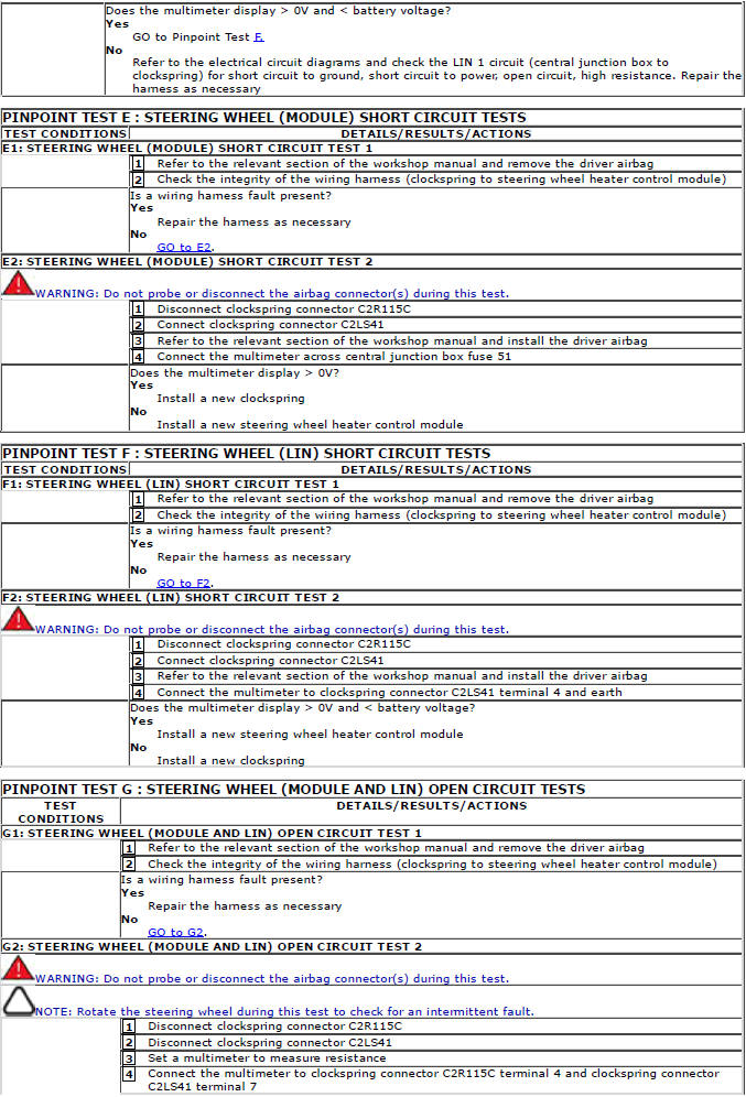
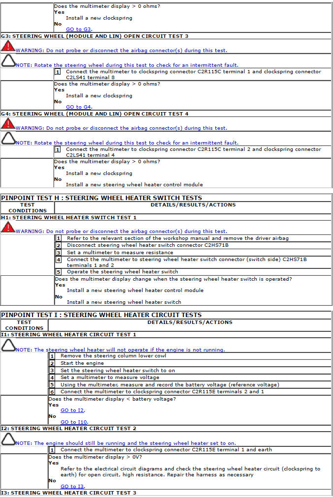
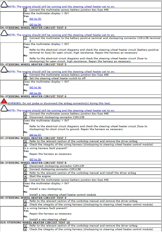
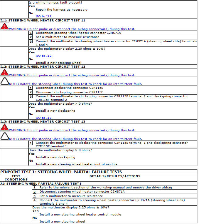
Pinpoint Tests
DTC Index
For a list of Diagnostic Trouble Codes (DTCs) that could be logged on this vehicle, please refer to Section 100-00.
READ NEXT:
 Steering Column Switches
Torque Specifications
Steering Column Multifunction Switch
Removal
NOTES:
Removal steps in this procedure may contain installation details.
Removal of the windshield wiper switch assembly is identic
Engine System - General Information
Cylinder Head Gasket Selection TD4
2.2L Diesel
Special Tool(s)
303-979
Measuring Bridge, Piston Protusion
1. CAUTION: Make sure that the surface is clean and
free of foreign material.
Zero the gauge o
SEE MORE:
Locking and arming the alarm
CAUTION: No modifications or
additions should be made to the
anti-theft system. Such changes could
cause the system to malfunction.
There are two levels of security:
- Single locking. With all doors and tailgate
closed, press the lock button on the Smart
Key once, to Single lock the vehicle
Single locking
Single locking secures the vehicle and prevents
the doors from being opened from outside. The
doors may still be unlocked and opened using
the interior door locks and release levers. In
this state, only the perimeter (exterior) alarm is
activated. When the vehicle is Single locked
and the alar
