Range Rover Evoque: Air Conditioning
Component Location
COMPONENT LOCATION
- High pressure line
- Low pressure servicing connection
- High pressure servicing connection
- Thermostatic expansion valve
- Evaporator
- Refrigerant pressure sensor
- Receiver/Drier
- Condenser
- A/C (air conditioning) compressor
- Low pressure line
COMPONENT LOCATION - VEHICLES WITH IHX
- IHX
- High pressure servicing connection
- Low pressure servicing connection
- Refrigerant pressure sensor
- Thermostatic expansion valve
- Evaporator
- Condenser
- Receiver/Drier
- A/C compressor
- Low pressure line
- High pressure line
Overview
OVERVIEW
The A/C (air conditioning) system transfers heat from the cabin to the outside atmosphere to provide the heater assembly with dehumidified cool air.
The A/C system is a sealed closed loop system, filled with a charge weight of R134a refrigerant as the heat transfer medium. The refrigerant charge weight for both the GTDi and the DW12C vehicles is 650g. Oil is added to the refrigerant to lubricate the internal components of the A/C compressor.
Despite the different units, the A/C compressors fitted to both the GTDi petrol engine and the DW12C diesel engine are both variable displacement units. The displacement (flow of refrigerant) is controlled to match the thermal load of the evaporator.
The operation of the A/C system is controlled by the ATC (automatic temperature control)
System Operation and Component Description
Control Diagram
NOTE: A = Refrigerant liquid; B = Refrigerant vapor; C = Air flow
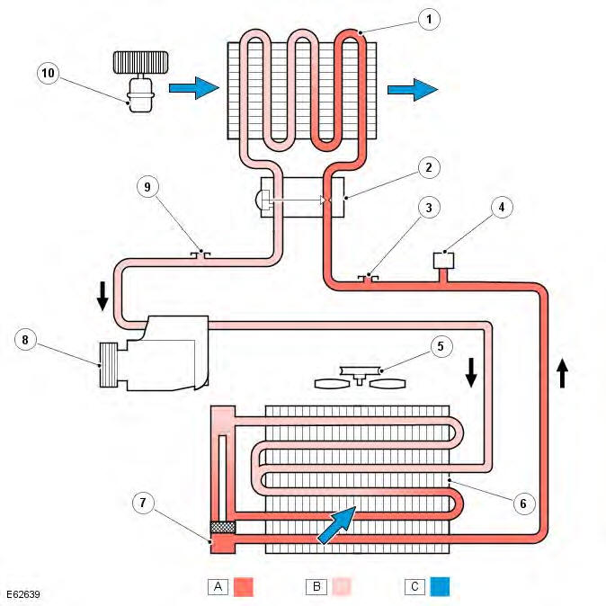
- Evaporator
- Thermostatic expansion valve
- High pressure servicing connection
- Refrigerant pressure sensor
- Engine cooling fan
- Condenser
- Receiver/Drier
- A/C (air conditioning) compressor
- Low pressure servicing connection
- Cooling fan
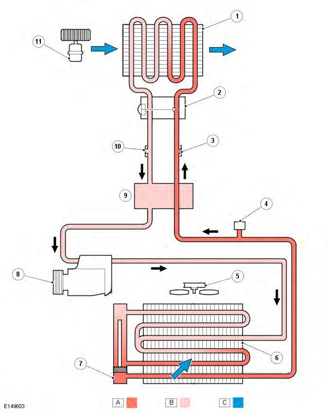
- Evaporator
- Thermostatic expansion valve
- High pressure servicing connection
- Refrigerant pressure sensor
- Engine cooling fan
- Condenser
- Receiver/Drier
- A/C compressor
- IHX
- Low pressure servicing connection
- Cooling fan
System Operation
PRINCIPLES OF OPERATION
To accomplish the transfer of heat, the refrigerant is circulated around the system, where it passes through 2 pressure/temperature regimes. In each of the regimes the refrigerant changes state, during which process maximum heat absorption or dissipation occurs.
The low pressure/temperature regime is from the thermostatic expansion valve, through the evaporator to the compressor.
The refrigerant decreases in pressure and temperature at the thermostatic expansion valve then changes state from a liquid to a vapour in the evaporator to absorb heat.
The high pressure/temperature regime is from the compressor, through the condenser and receiver drier assembly to the thermostatic expansion valve. The refrigerant increases in pressure and temperature as it passes through the compressor, then releases heat and changes state from a vapour to a liquid in the condenser.
The operation of the A/C system is controlled by the ATC (automatic temperature control) Refer to: Control Components (412-01 Climate Control, Description and Operation).
Component Description
A/C COMPRESSOR
GTDi
DW12C
GTDi/DW12C compressors
The A/C compressor is driven by the engine accessory drive belt and circulates refrigerant around the system by compressing low pressure, low temperature vapor from the evaporator and discharging the resultant high pressure, high temperature vapor to the condenser.
To protect the system from excessive pressure, a pressure relief valve is installed in the outlet side of the A/C compressor.
The pressure relief valve vents excess pressure into the engine compartment.
Both vehicles are fitted with a variable displacement A/C compressor. Displacement is controlled internally by a control valve, which is integral with the compressor. The control valve measures the input and output pressures of the refrigerant entering and leaving the compressor and controls the angle of the internal swash plate accordingly.
NOTE: There is no external control over A/C compressor swash plate angle. Consequently, compressor displacement is neither measured nor calculated by any external control component.
Compressor clutch engagement is controlled by the ECM (engine control module).
Refer to: Control Components (412-01 Climate Control, Description and Operation).
CONDENSER
- Condenser
- Receiver/Drier
The condenser transfers heat from the refrigerant to the surrounding air to convert the high pressure vapor from the compressor into a liquid. The condenser is installed immediately in front of the radiator. Two brackets on each end tank attach the condenser to the end tanks of the radiator.
The condenser is classified as a sub-cooling condenser and consists of a fin and tube heat exchanger core installed between 2 end tanks. Divisions in the end tanks separate the heat exchanger into a 4 pass upper (condenser) section and a 2 pass lower (sub-cooler) section.
The RH (right-hand) end tank provides the connections to the high pressure line from the A/C compressor and the low pressure line to the evaporator.
RECEIVER/DRIER
The receiver/drier is integral with the condenser LH (left-hand) end tank and removes solid impurities and moisture from the refrigerant. It also acts as a reservoir for liquid refrigerant to accommodate changes of heat load at the evaporator.
Refrigerant entering the receiver drier passes through a filter and a desiccant pack, then collects in the base of the unit before flowing through the outlet pipe back to the condenser.
REFRIGERANT PRESSURE SENSOR
The refrigerant pressure sensor provides the ATC module with a pressure input from the high pressure side of the refrigerant system. The refrigerant pressure sensor is hardwired to the ECM, which uses the signal to control operation of the A/C compressor and to calculate the additional load on the engine when the A/C compressor is operating. The ECM also broadcasts the refrigerant high pressure value over the high speed CAN (controller area network) bus to the CJB (central junction box). The CJB relays the signal to the ATC module over the medium speed CAN bus to increase the amount of re-circulated air if required.
The refrigerant pressure sensor is located in the refrigerant line between the condenser and the thermostatic expansion valve.
Refer to: Control Components (412-01 Climate Control, Description and Operation).
THERMOSTATIC EXPANSION VALVE
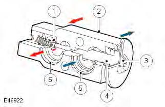
- Metering valve
- Housing
- Diaphragm
- Temperature sensor
- Outlet passage from evaporator
- Inlet passage to evaporator
The thermostatic expansion valve meters the flow of refrigerant into the evaporator, to match the refrigerant flow with the heat load of the air passing through the evaporator.
The thermostatic expansion valve is a block type valve located behind the heater assembly, and attached to the inlet and outlet ports of the evaporator. The thermostatic expansion valve consists of an aluminum housing containing inlet and outlet passages. A ball and spring metering valve is installed in the inlet passage and a temperature sensor is installed in the outlet passage. The temperature sensor consists of a temperature sensitive tube connected to a diaphragm. The bottom end of the temperature sensitive tube acts on the ball of the metering valve. Pressure on top of the diaphragm is controlled by the evaporator outlet temperature conducted through the temperature sensitive tube. The bottom of the diaphragm senses evaporator outlet pressure.
Liquid refrigerant flows through the metering valve into the evaporator. The restriction across the metering valve reduces the pressure and temperature of the refrigerant. The restriction also changes the liquid stream of refrigerant into a fine spray, to improve the evaporation process. As the refrigerant passes through the evaporator, it absorbs heat from the air flowing through the evaporator. The increase in temperature causes the refrigerant to vaporize and increase in pressure.
The temperature and pressure of the refrigerant leaving the evaporator acts on the diaphragm and temperature sensitive tube, which regulate the metering valve opening and so control the volume of refrigerant flowing through the evaporator.
The warmer the air flowing through the evaporator, the more heat available to evaporate refrigerant and thus the greater volume of refrigerant allowed through the metering valve.
EVAPORATOR
The evaporator is installed in the heater assembly, between the blower and the heater core, to absorb heat from the exterior or re-circulated air. Low pressure, low temperature refrigerant changes from liquid to vapor in the evaporator, absorbing large quantities of heat as it changes state.
Most of the moisture in the air passing through the evaporator condenses into water, which drains out of the vehicle by passing through a drain tube to the underside of the vehicle.
REFRIGERANT LINES
To maintain similar flow velocities around the A/C system the diameter of the refrigerant lines varies to suit the 2 pressure/temperature regimes. Larger diameter pipes are installed in the low pressure/temperature regime and smaller diameter pipes are installed in the high pressure/temperature regime.
Nylon lined, low permeability rubber hoses are used in the low pressure line into the A/C compressor, and in the high pressure line from the condenser. The remainder of the refrigerant lines is manufactured from aluminum.
Low and high pressure charging connections are incorporated into the refrigerant lines for system servicing.
INTERNAL HEAT EXCHANGER
- High pressure line
- Low pressure line
- IHX
The Internal Heat Exchanger (IHX) is incorporated within the air conditioning pipes.
The IHX is part of the vehicle's air conditioning system and helps to increase its cooling capacity. The IHX combines a section of the system's pipework before and after the evaporator into one pipe. It uses the cold vapour exiting the evaporator to cool the hot liquid before it enters the expansion device, resulting in increased cooling. It also uses the heat to increase the temperature of the low temperature gas before it enters the compressor. The amount of energy used by the air conditioning system can be reduced by taking advantage of this increased cooling.
This gives the following benefits:
- Helps reduce tailpipe CO2 emissions, due to less engine load.
- Improved fuel economy, due to reduced compressor power requirements.
- R1234yf - Increases the system capacity to increase cooling.
NOTE: Due to a drop in performance of the R1234yf system when compared to the R134a system an Internal Heat Exchanger (IHX) is installed, this has the effect of increasing the system capacity.
READ NEXT:
 Control Components - Component Location
Component Location
COMPONENT LOCATION (GTDI)
Refrigerant pressure sensor
Cabin humidity sensor (if fitted)
A/C (air conditioning) compressor
ECT (engine coolant temperature) sensor
Ambient air
Control Diagram, System Operation
Control Diagram
NOTE: A = Hardwired; D = High Speed CAN (controller area network) bus; N =
Medium Speed CAN bus; O = LIN
(local interconnect network) bus
DW12C is shown, GTDi is similar
Battery
B
SEE MORE:
Electric seats
Electric seats
1. Lumbar support adjustment.
2. Backrest adjustment.
3. Head restraint adjustment.
4. Height adjustment.
5. Forward and back adjustment.
6. Cushion angle adjustment.
To adjust the seats, the Smart Key must be
inside the vehicle.
Do not adjust
the seat while the
vehicle
Stalled adjustment
If seat
movement stops unexpectedly
during adjustment check for any
obstructions and remove.
Once any obstructions have been removed the
seat adjustment mechanism can be reset as
follows.
Operate the button again to continue the stalled
adjustment. When seat movement resumes
hold the butt
