Range Rover Evoque: Control Diagram, System Operation
Control Diagram
NOTE: A = Hardwired; D = High Speed CAN (controller area network) bus; N = Medium Speed CAN bus; O = LIN (local interconnect network) bus
DW12C is shown, GTDi is similar
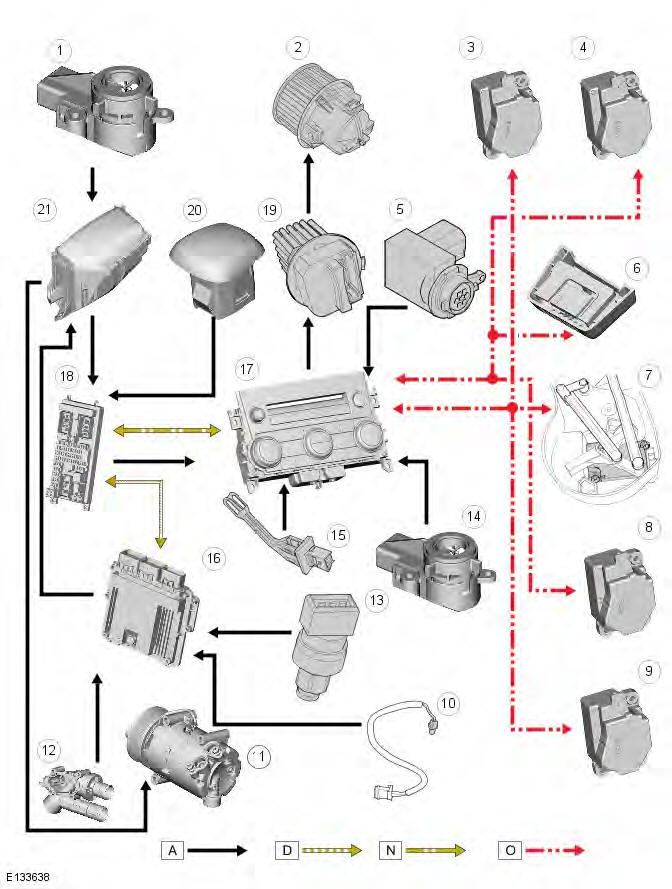
- Battery
- Blower motor
- LH (left-hand) temperature blend stepper motor
- Windshield distribution (defrost) stepper motor
- Pollution sensor
- Cabin humidity sensor
- Air intake stepper motor
- RH (right-hand) temperature blend stepper motor
- Face/feet distribution stepper motor
- Ambient air temperature sensor
- A/C (air conditioning) compressor pressure control valve
- ECT (engine coolant temperature) sensor
- Refrigerant pressure sensor
- Cabin temperature sensor
- Evaporator temperature sensor
- ECM (engine control module) module
- ATC (automatic temperature control)
- CJB (central junction box)
- Blower motor control module
- Sunload sensor
- BJB (battery junction box)
System Operation
Intake Air Control - Dual Zone Automatic System
The intake air source is controlled automatically unless overridden by pressing the fresh/re-circulated air switch located on the control panel. Under automatic control, the ATC module determines the required position of the air intake door using its 'comfort' algorithm based on inputs from the ambient air temperature sensor and the cabin temperature sensor.
When the vehicle first enters power mode 6 (ignition on), the tell-tale LED (light emitting diode) on the fresh/re-circulated air switch will be illuminated and the air intake source will be automatically controlled by the ATC module. The ATC module will control the intake air source according to ambient air temperature and requested cabin temperature. The intake air door will be opened to allow fresh air into the cabin, although a small amount of re-circulated air will also be present.
NOTE: The ATC module will reduce the amount of fresh air entering the cabin to reduce the ram effect caused by forward motion of the vehicle.
A single press of the fresh/re-circulated air switch will illuminate the tell-tale 'MAN' LED. The ATC module will now close the air intake door and provide only re-circulated air into the cabin for a period of 3 minutes. After this period, the ATC module will return the air intake door to automatic control. This helps prevent misting within the cabin.
A second press of the fresh/re-circulated air switch will also return the intake air source to automatic control and illuminate the tell-tale 'AUTO' LED.
The 3 minute time period for re-circulated air can be overridden by pressing and holding the fresh/re-circulated air switch until the switch LED flashes 3 times. The air intake door will now remain closed until the next drive cycle.
The ATC module controls the position of the air intake door by providing LIN bus messages to the air intake door stepper motor. A Hall effect sensor located within the stepper motor informs the ATC module that movement of the stepper motor is taking place.
Intake Air Control - Dual Zone Automatic System with Pollution Sensor
The intake air source is controlled automatically unless overridden by pressing the fresh/re-circulated air switch located on the control panel. Under automatic control, the ATC module determines the required position of the air intake door using its 'comfort' algorithm based on inputs from the ambient air temperature sensor, the cabin temperature sensor and the pollution sensor.
NOTE: The ATC module will reduce the amount of fresh air entering the cabin to reduce the ram effect caused by forward motion of the vehicle.
When the vehicle first enters power mode 6 (ignition on), the 'AUTO' tell-tale LED on the fresh/re-circulated air switch will be illuminated and the air intake source will be automatically controlled by the ATC module. A single press of the fresh/recirculated air switch will extinguish the 'AUTO' tell-tale LED and illuminate the 'MAN' tell-tale LED. The ATC module will now close the air intake door and provide only re-circulated air into the cabin for a period of 3 minutes. After this period, the ATC module will return the air intake door to automatic control. This helps prevent misting within the cabin.
A second press of the fresh/re-circulated air switch will extinguish both the 'AUTO' and 'MAN' tell-tale LED's. The ATC module will now control the intake air source according to ambient air temperature and requested cabin temperature. The air intake door will be opened to allow fresh air into the cabin, but a small amount of re-circulated air will also be present.
The amount of re-circulated air is determined by the ATC module using its 'comfort' algorithm based on inputs from the ambient air temperature sensor and the cabin temperature sensor.
A third press of the fresh/re-circulated air switch returns the air intake source to automatic control and will illuminate the 'AUTO' tell-tale LED.
The 3 minute time period for re-circulated air can be overridden by pressing and holding the fresh/re-circulated air switch until the switch LED's flash 3 times. The air intake door will now remain closed until the next drive cycle.
The ATC module controls the position of the air intake door by providing LIN bus messages to the air intake door stepper motor. A Hall effect sensor, located within the stepper motor, informs the ATC module that movement of the stepper motor is taking place.
Air Temperature Control - Dual Zone Automatic System
Dual zone systems feature 2 rotary heating controllers, which allow individual climate control for the LH and RH sides of the cabin. Temperature selection can be made by turning the controller to the required temperature marked on the control panel. Turning either controller past the 16
READ NEXT:
 Component Description
ATC MODULE
NOTE: The 'ECON' button has been renamed 'A/C' to prevent confusion with
the Stop/Start system 'Eco' switch.
The ATC module is mounted in the center console and is integral with the
cont
Condenser GTDi 2.0L Petrol
Removal
CAUTION: Make sure that all openings are sealed. Use new blanking caps.
NOTES:
Some variation in the illustrations may occur, but the essential information is
always correct.
Removal steps
Blower Motor LHD AWD/LHD FWD
Special Tool(s)
412-140
Remover/Installer, Blower Motor
Removal
NOTES:
Removal steps in this procedure may contain installation details.
Some variation in the illustrations may occur, but the essenti
SEE MORE:
Important information
The information contained in this handbook covers all vehicle derivatives and
optional equipment,
some of which may not be fitted to your vehicle. Due to printing cycles, this
handbook may include
descriptions of options before they become generally available.
The vehicle options, hardware an
Symbols used in this handbook
Safety warnings indicate either a procedure which must be followed
precisely, or
information that should be considered with great care, in order to avoid the
possibility
of personal injury.
Cautions indicate either a procedure which must be followed precisely, or
information that
should
