Range Rover Evoque: Blower Motor LHD AWD/LHD FWD
Special Tool(s)
 412-140
Remover/Installer, Blower Motor
Removal
NOTES: Removal steps in this procedure may contain installation details.
Some variation in the illustrations may occur, but the essential information is always correct.
1. NOTE: The recirculation blend door must be closed in order for the removal of the recirculation blend door housing. Activate recirculation.
2. Disconnect the battery ground cable.
Refer to: Specifications (414-01 Battery, Mounting and Cables, Specifications).
3. Refer to: Accelerator Pedal (310-02 Acceleration Control, Removal and Installation).
4. Refer to: Central Junction Box (CJB) (418-00 Module Communications Network, Removal and Installation).
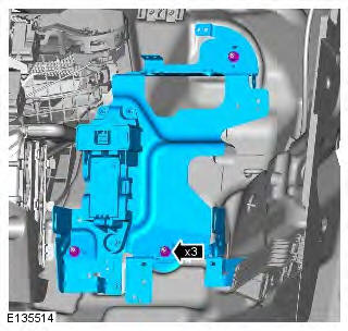
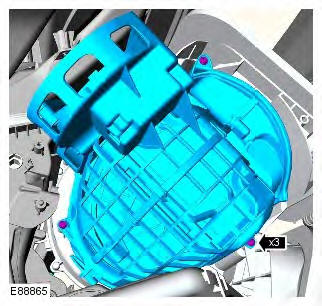
5.
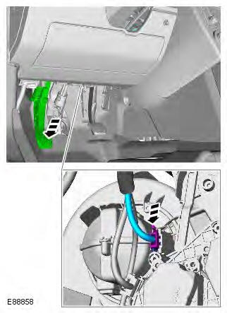
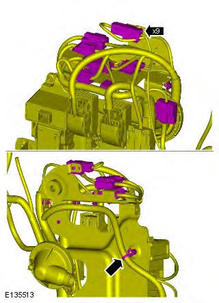
6.
7.
8. Torque: 10 Nm
9.
10.
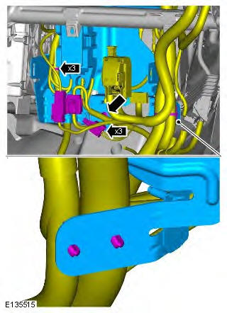
11.
12.
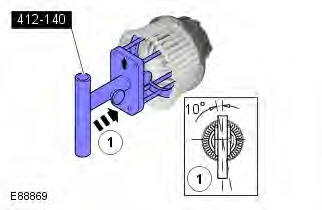
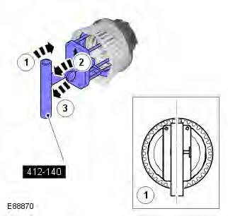
13. Special Tool(s): 412-140
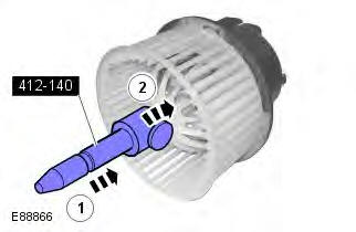
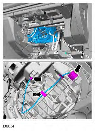
14.
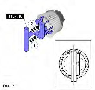
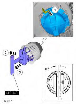
15. CAUTION: Make sure that the special tool is correctly located.
NOTE: With assistance remove the component.
Installation
1.
2.
3. To install, reverse the removal procedure.
READ NEXT:
 Blower Motor RHD AWD/RHD FWD, RHD
Special Tool(s)
412-140
Remover/Installer, Blower Motor
Removal
NOTES:
Removal steps in this procedure may contain installation details.
Some variation in the illustrations may occur, but the essenti
Climate Control Assembly
Removal
NOTE: Removal steps in this procedure may contain installation details.
All vehicles
1. CAUTION: LH illustration shown, RH is similar.
NOTE: The procedure must be carried out on both
sides.
Evaporator LHD
Removal
NOTES:
The removal of this component involves cutting an aperture in the evaporator
housing wall and cutting through the
high and low pressure A/C lines. A service repair kit is supplied to c
SEE MORE:
Component Description
Parking Aid Module
The parking aid module is located on the LH side of the luggage compartment,
behind the 'C' pillar trim panel.
The parking aid module has three connectors which provide for power, ground and
CAN bus connections, front parking aid
sensors and rear parking aid sensors.
The high
Front Inner Parking Aid Sensor
Removal
CAUTION: LH illustration shown, RH is similar.
NOTES:
Removal steps in this procedure may contain installation details.
The ignition must be switched off.
1. WARNING: Make sure to support the vehicle with axle stands.
Raise and support the vehicle.
2. Refer to: Front Bumper Cover (501-19 B
