Range Rover Evoque: Control Diagram
NOTES:
A = Hardwired; N = Medium Speed CAN (controller area network) bus; D = High Speed CAN bus; T = Coaxial; O = LIN (local interconnect network) bus; P = Fibre Optic MOST; AD = NSTC; AE = LVDS;
Park assist is not available to all markets.
CONTROL DIAGRAM - SHEET 1 OF 3 - PARKING AID AND PARK ASSIST
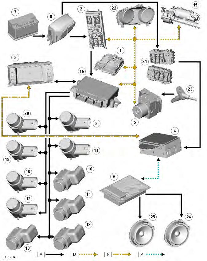
- TCM (transmission control module)
- CJB (central junction box)
- Integrated Control Panel (ICP)
- Integrated Audio Module (IAM)
- ABS (anti-lock brake system) module
- Audio power amplifier (Hi-Line only)
- Battery
- BJB (battery junction box)
- LH (left-hand) side parking aid sensor
- LH front outer parking aid sensor
- LH front inner parking aid sensor
- RH (right-hand) front inner parking aid sensor
- RH front outer parking aid sensor
- RHside parking aid sensor
- Electric power assisted steering rack
- Park distance control module
- RH rear outer parking aid sensor
- RH rear inner parking aid sensor
- LH rear inner parking aid sensor
- LH rear outer parking aid sensor
- RJB (rear junction box)
- Instrument cluster
- Wheel speed sensors
- Front audio speakers
- Rear audio speakers
CONTROL DIAGRAM - SHEET 2 OF 3 - REAR VIEW CAMERA SYSTEM (LOW-LINE)
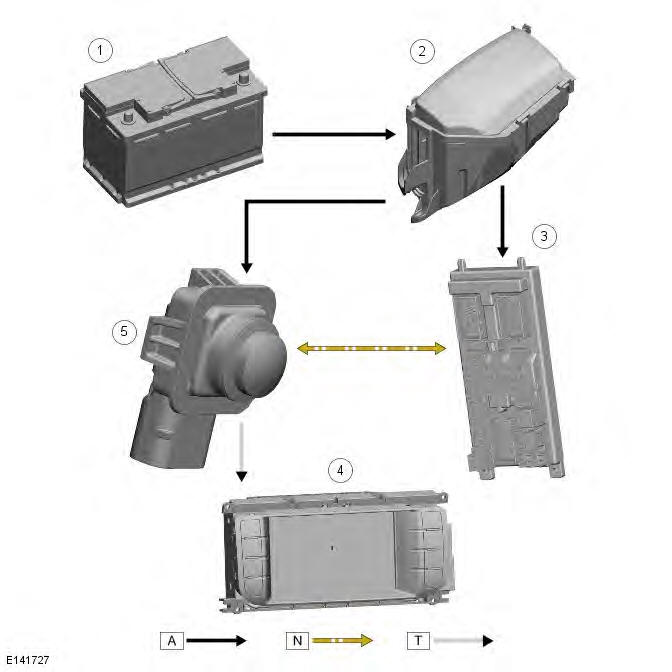
- Battery
- BJB
- CJB
- Touch Screen Display (TSD)
- Rear view camera
CONTROL DIAGRAM - SHEET 3 OF 3 - PROXIMITY CAMERA SYSTEM (HI-LINE)
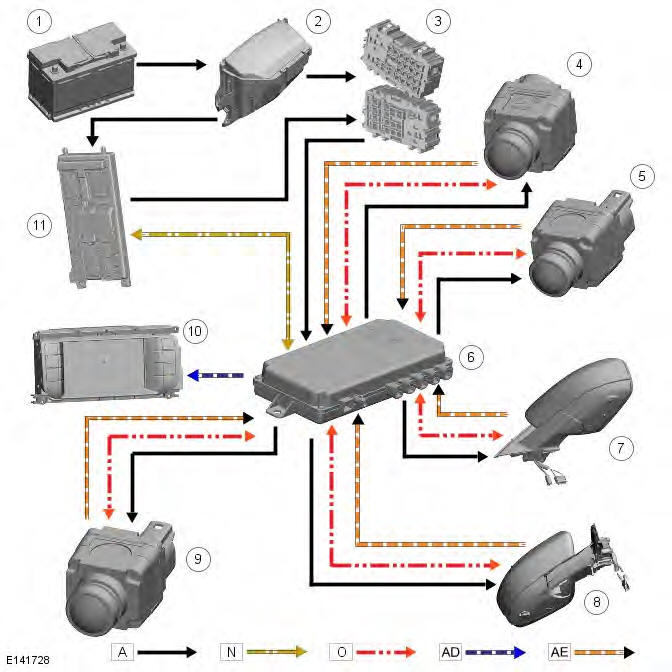
- Battery
- BJB
- RJB
- Front bumper camera
- Front bumper camera
- Proximity camera control module
- Mirror camera
- Mirror camera
- Rear view camera
- Touch Screen Display (TSD)
- CJB
READ NEXT:
 System Operation
PRINCIPLES OF OPERATION - PARKING AID
Vehicles Fitted With Automatic Transmission
If reverse ) is the first gear selected after the ignition is switched on,
both the front (if fitted) and rear parkin
Component Description
Parking Aid Module
The parking aid module is located on the LH side of the luggage compartment,
behind the 'C' pillar trim panel.
The parking aid module has three connectors which provide for power
Front Inner Parking Aid Sensor
Removal
CAUTION: LH illustration shown, RH is similar.
NOTES:
Removal steps in this procedure may contain installation details.
The ignition must be switched off.
1. WARNING: Make sure to support th
SEE MORE:
Electric parking brake (EPD)
The parking brake operates on
the rear
wheels. Therefore, secure parking of
the vehicle is dependent on being on a
hard and stable surface.
Do not rely on the parking brake to
operate effectively, if the rear wheels
have been immersed in mud or water.
Note: If the vehicle is used in severe
Epb manual use
Epb manual use
1. To apply the parking brake, with the vehicle
stationary, pull up the lever and release it.
The parking brake warning
lamp will illuminate. It is
important to confirm that the
lamp is continuously illuminated (not
flashing), as this indicates the brake has
been correctly
© 2011-2026 Copyright www.rrevoque.org - 0.0038
