Range Rover Evoque: Engine - Diagnosis and Testing
Principles of Operation
For a detailed description of the engine system, refer to the relevant Description and Operation section in the workshop manual. REFER to: (303-01B Engine - GTDi 2.0L Petrol)
Inspection and Verification
CAUTION: Diagnosis by substitution from a donor vehicle is NOT acceptable. Substitution of control modules does not guarantee confirmation of a fault and may also cause additional faults in the vehicle being checked and/or the donor vehicle.
1. Verify the customer concern.
2. Visually inspect for obvious signs of mechanical or electrical damage.
Visual Inspection
3. If an obvious cause for an observed or reported concern is found, correct the cause (if possible) before proceeding to the next step
4. If the cause is not visually evident, verify the symptom and refer to the Symptom Chart.
Symptom Chart
NOTES:
If an engine is suspect, when the vehicle remains under the Manufacturers warranty refer to the Warranty Policy and Procedure manual (section B1.2), or determine if any prior approval programme is in operation, prior to the installation of a new engine.
Due to the possibility of loose carbon, that has become trapped between the valve face and seat, effecting the pressure readings, when carrying out a compression test and some cylinders are found to have low pressures, install the spark plugs, road test the vehicle and re-test the suspect cylinders. If the correct pressures are restored, no further action is required.
Component Tests
Engine Oil Leaks
NOTE: Before installing new gaskets or oil seals, make sure that the fault is clearly established.
If the oil leak cannot be identified clearly by a visual inspection, carry out an Ultraviolet test:
Fluorescent Oil Additive Method
1. Clean the engine with a suitable cleaning fluid (brake cleaner).
2. Drain the engine oil and refill with recommended oil, premixed with Engine Oil Dye or equivalent. Use a minimum 14.8 ml (0.5 ounce) to a maximum 29.6 ml (1 ounce) of fluorescent additive to all engines. If oil is not premixed, fluorescent additive must first be added to the crankcase.
3. Run engine for 15 minutes. Stop the engine and inspect all seal and gasket areas for leaks using a 12 Volt Master UV Diagnostic Inspection Kit or equivalent. A clear bright yellow or orange area will identify leak. For extremely small leaks, several hours may be required for the leak to appear.
4. As necessary, pressurize the main oil gallery system to locate leaks due to incorrectly sealed, loose or cocked plugs. If the flywheel bolts leak oil, look for sealer on the threads.
5. Repair all leaks as necessary.
Compression Test
General Remarks
NOTES:
Removing fuses and disconnecting electrical components may cause the Engine Control Module (ECM) to log Diagnostic Trouble Codes (DTCs). After the measurements have been carried out, DTCs should be cleared from memory by connecting to the Manufacturer Approved Diagnostic System.
Only check the compression pressure with the valves set to the prescribed clearance (if this can be adjusted).
The compression pressure should be checked with the engine at operating temperature.
Check the Compression Pressure
WARNING: Move gear selector lever to 'P' position. Failure to follow this instruction may result in personal injury.
1. Remove the fuel pump relay.
2. Start the engine - the engine will start, run for a few seconds then stop.
3. Remove the spark plugs.
4. Install the compression tester.
5. Install an auxiliary starter switch in the starting circuit. With the ignition switch OFF, using the auxiliary starter switch, crank the engine a minimum of five compression strokes and record the highest reading. Note the approximate number of compression strokes required to obtain the highest reading.
6. Repeat the test on each cylinder, cranking the engine approximately the same number of compression strokes.
7. Install the removed components in reverse order, observing the specified tightening torques.
8. Clear all DTCs from the ECM.
Interpretation of the Results
NOTE: Due to the possibility of loose carbon that has become trapped between the valve face and seat effecting the pressure readings, when carrying out a compression test and cylinders are found to have low pressures, install the spark plugs, road test the vehicle and re-test the suspect cylinders. If the correct pressures are restored, no further action is required.
The indicated compression pressures are considered within specification if the lowest reading cylinder is within 75% of the highest reading.
If the cylinder pressures are found to be low, carry out a leakdown test to determine the location of the fault (if any leakback can be heard through the engine breather system suspect the piston rings, if any leakback can be heard through the inlet system suspect the inlet valve or seat, if any leakback can be heard through the exhaust manifold suspect the exhaust valve or seat. If the measurements for two cylinders next to each other are both too low then it is very likely that the cylinder head gasket between them is burnt through. This can also be recognized by traces of engine oil in the coolant and/or coolant in the engine oil).
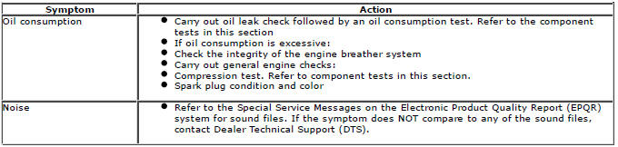
Oil Consumption Test
The amount of oil an engine uses will vary with the way the vehicle is driven in addition to normal engine-to-engine variation. This is especially true during the first 16,100 km (10,000 miles) when a new engine is being broken in or until certain internal components become conditioned. Vehicles used in heavy-duty operation may use more oil. The following are examples of heavy-duty operation:
- Trailer towing applications
- Severe loading applications
- Sustained high speed operation
Engines need oil to lubricate the following internal components:
- Cylinder block cylinder walls
- Pistons and piston rings
- Intake and exhaust valve stems
- Intake and exhaust valve guides
- All internal engine components
When the pistons move downward, a thin film of oil is left on the cylinder walls. As the vehicle is operated, some oil is also drawn into the combustion chambers past the intake and exhaust valve stem seals and burned.
The following are examples of conditions that can affect oil consumption rates:
- Engine size
- Operator driving habits
- Ambient temperatures
- Quality and viscosity of oil
- Engine is being run in an overfilled condition (check the oil level at least five minutes after a hot shutdown with the vehicle parked on a level surface. The oil level should not be above the Full mark).
Operation under varying conditions can frequently be misleading. A vehicle that has been run for several thousand miles on short trips or in below-freezing ambient temperatures may have consumed a "normal" amount of oil. However, when checking the engine oil level, it may measure up to the full mark on the oil level indicator due to dilution (condensation and fuel) in the engine crankcase. The vehicle then might be driven at high speeds on the highway where the condensation and fuel boil off. The next time the engine oil is checked it may appear that a liter of oil was used in about 160 km (100 miles). Oil consumption rate is about one liter per 2,400 km (1,500 miles).
Make sure the selected engine oil meets manufacturer specification and the recommended API performance category "SG" and SAE viscosity grade as shown in the vehicle Owner's Guide. It is also important that the engine oil is changed at the intervals specified for the typical operating conditions.
The following diagnostic procedure is used to determine the source of excessive oil consumption.
NOTE: Oil use is normally greater during the first 16,100 km (10,000 miles) of service. As mileage increases, oil use decreases. High speed driving, towing, high ambient temperature and other factors may result in greater oil use.
1. Define excessive consumption, such as the number of miles driven per liter of oil used. Also determine customers driving habits, such as sustained high speed operation, towing, extended idle and other considerations.
2. Verify that the engine has no external oil leaks as described under Engine Oil Leaks in this section.
3. Carry out an oil consumption test:
- Run the engine to normal operating temperature. Switch engine OFF and allow oil to drain back for at least five minutes .
- With vehicle parked on level surface, check the engine oil level.
- If required, add engine oil to set level exactly to the FULL mark.
- Record the vehicle mileage.
- Instruct the customer to return for a level check after driving the vehicle as usual for 1,610 km (1000 miles).
- Check the oil level under the same conditions and at the same location as the initial check.
NOTE: If the oil consumption rate is unacceptable go to Step 4.
4. Check the Positive Crankcase Ventilation (PCV) system. Make sure the system is not plugged.
5. Check for plugged oil drain-back holes in the cylinder head and cylinder block.
6. Carry out a cylinder compression test. Refer to the Compression Test procedure in this section. This can help determine the source of oil consumption such as valves, piston rings or other areas.
7. Check valve guides for excessive guide clearance. Install new valve stem seals after verifying valve guide clearance.
8. Worn or damaged internal engine components can cause excessive oil consumption. Small deposits of oil on the tips of the spark plugs can be a clue to internal oil consumption.
Intake Manifold Vacuum Test
Bring the engine to normal operating temperature. Connect a vacuum gauge or equivalent to the intake manifold. Run the engine at the specified idle speed.
The vacuum gauge should read between 51-74 kPa (15-22 in-Hg) depending upon the engine condition and the altitude at which the test is performed. Subtract 4.0193 kPa (1 in-Hg) from the specified reading for every 304.8 m (1,000 feet) of elevation above sea level.
The reading should be steady. As necessary, adjust the gauge damper control (where used) if the needle is fluttering rapidly. Adjust damper until needle moves easily without excessive flutter.
Interpreting Vacuum Gauge Readings
A careful study of the vacuum gauge reading while the engine is idling will help pinpoint trouble areas. Always conduct other appropriate tests before arriving at a final diagnostic decision. Vacuum gauge readings, although helpful, must be interpreted carefully.
Most vacuum gauges have a normal band indicated on the gauge face.
The following are potential gauge readings. Some are normal; others should be investigated further.
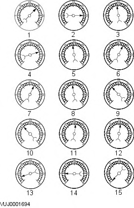
- NORMAL READING: Needle between 51-74 kPa (15-22 in-Hg) and holding steady.
- NORMAL READING DURING RAPID ACCELERATION: When the engine is rapidly accelerated, the needle will drop to a low (not to zero) reading. When the throttle is suddenly released, the needle will snap back up to a higher than normal figure.
- NORMAL FOR HIGH-LIFT CAMSHAFT WITH LARGE OVERLAP: The needle will register as low as 51 kPa (15 in-Hg) but will be relatively steady. Some oscillation is normal.
- WORN RINGS OR DILUTED OIL: When the engine is accelerated, the needle drops to 0 kPa (0 in-Hg). Upon deceleration, the needle runs slightly above 74 kPa (22 in-Hg).
- STICKING VALVES: When the needle remains steady at a normal vacuum but occasionally flicks (sharp, fast movement) down and back about 13 kPa (4 in-Hg), one or more valves may be sticking.
- BURNED OR BENT VALVES: A regular, evenly-spaced, downscale flicking of the needle indicates one or more burned or damaged valves. Insufficient hydraulic valve tappet or hydraulic lash adjuster clearance will also cause this reaction.
- POOR VALVE SEATING: A small but regular downscale flicking can mean one or more valves are not seating correctly.
- WORN VALVE GUIDES: When the needle oscillates over about a 13 kPa (4 in-Hg) range at idle speed, the valve guides could be worn. As engine speed increases, the needle will become steady if guides are responsible.
- WEAK VALVE SPRINGS: When the needle oscillation becomes more violent as engine RPM is increased, weak valve springs are indicated. The reading at idle could be relatively steady.
- LATE VALVE TIMING: A steady but low reading could be caused by late valve timing.
- IGNITION TIMING RETARDED: Retarded ignition timing will produce a steady but somewhat low reading.
- INSUFFICIENT SPARK PLUG GAP: When spark plugs are gapped too close, a regular, small pulsation of the needle can occur.
- INTAKE LEAK: A low, steady reading can be caused by an intake manifold or throttle body gasket leak.
- BLOWN HEAD GASKET: A regular drop of fair magnitude can be caused by a blown head gasket or warped cylinder head to cylinder block surface.
- RESTRICTED EXHAUST SYSTEM: When the engine is first started and is idled, the reading may be normal, but as the engine RPM is increased, the back pressure caused by a clogged muffler, kinked tail pipe or other concerns will cause the needle to slowly drop to 0 kPa (0 in-Hg). The needle then may slowly rise. Excessive exhaust clogging will cause the needle to drop to a low point even if the engine is only idling.
When vacuum leaks are indicated, search out and correct the cause. Excess air leaking into the system will upset the fuel mixture and cause concerns such as rough idle, missing on acceleration or burned valves. If the leak exists in an accessory such as the power brake booster, the unit will not function correctly. Always repair vacuum leaks.
Engine Oil Pressure Check
NOTE: Prior to checking the engine oil pressure, a road test of 6 miles (10 kilometres), must be carried out. Do not attempt to attain engine normal operating temperature by allowing the engine to idle.
1. Disconnect the battery ground cable. REFER to: REFER to: Battery (414-01 Battery, Mounting and Cables, Removal and Installation).
2. WARNINGS:
The spilling of hot engine oil is unavoidable during this procedure, care must be taken to prevent scalding.
Wear protective gloves.
Remove the engine oil pressure sensor.
3. Connect the oil pressure gauge and adaptor in place of the oil pressure sensor.
4. Check and top-up the engine oil if required.
5. Connect the battery ground cable. REFER to: REFER to: Battery (414-01 Battery, Mounting and Cables, Removal and Installation).
6. Start and run the engine.
NOTES:
Measure the oil pressure at the specified engine speed. Measure the oil pressure at normal operating temperature.
Oil pressure at 800 rev/min: 1.6 bar.
Oil pressure at 4000 rev/min: 3.1 bar.
7. Check the oil pressure.
8. Turn off the engine.
9. Disconnect the battery ground cable.
10. Remove the special tools.
- Clean the components.
11. Install the oil pressure sensor.
12. Check and top-up the engine oil if required.
13. Connect the battery ground cable.
DTC Index
For a complete list of all Diagnostic Trouble Codes (DTCs) that could be logged on this vehicle, please refer to Section 100-00. REFER to: Diagnostic Trouble Code (DTC) Index - GTDi 2.0L Petrol, DTC: Engine Control Module (ECM) (100-00 General Information, Description and Operation).
READ NEXT:
 Engine Timing
Special Tool(s)
303-1565
Locking Tool, Camshaft
308-511
Installer, Transmission Output Shaft Seal
JLR-303-1594
Locking Tool, Driveplate
JLR-303-748
Locking Tool, Crankshaft
Activation
1.
2. Install t
Engine Cooling - Component Location, System Operation and
Component Description
Component Location
COMPONENT LOCATION
Heater core
Air Conditioning (A/C) Evaporator (ref only)
Heater inlet hose
Heater outlet hose/Oil cooler inlet hose
Turbocharger water outlet pipe
Water o
SEE MORE:
Keyless locking
Never double lock the vehicle
with
people, children or pets inside. In the
event of an emergency they would be
unable to escape and the emergency
services would be unable to release
them quickly.
The Smart Key may not be
detected if it
is placed within a metal container or if it
is shi
Selecting valet mode
Valet mode allows the vehicle to be driven, e.g.,
by a parking attendant, but leaves the tailgate
locked and restricts use of the touch screen.
This prevents access to telephone numbers,
navigation addresses and audio system
settings.
From the Home menu, select Valet:
Enter a four digit Perso
