Range Rover Evoque: Evaporative Emissions - GTDi 2.0L Petrol
Evaporative Emissions - Component Location
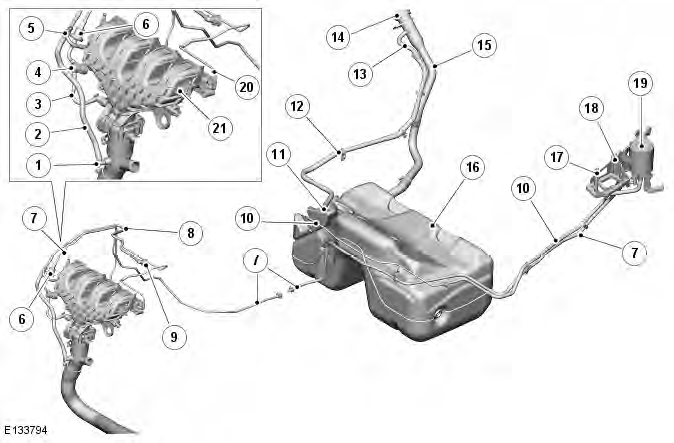
COMPONENT LOCATION ROW

- Clean air purge 2 hose connection
- Clean air purge 2 hose
- Vapor purge 3 hose from purge valve
- Double check valve
- Venturi
- Purge valve
- Purge hose from charcoal canister
- Clean air purge hose
- Clean air purge hose connection with clean air intake upper duct
- Fuel tank vent hose to charcoal canister
- Fuel pump module (hidden)
- Fuel tank breather pipe
- Fuel tank breather pipe - upper
- Fuel tank filler cap
- Fuel tank filler pipe
- Fuel tank assembly
- Spider trap
- Charcoal canister bracket
- Charcoal canister
- Turbocharger vacuum hose (Ref only)
- Intake manifold
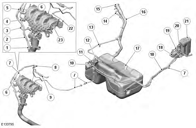
COMPONENT LOCATION NAS

- Clean air purge 2 hose connection
- Clean air purge 2 hose
- Vapor purge 3 hose from purge valve
- Double check valve
- Venturi
- Purge valve
- Purge hose from charcoal canister
- Clean air purge hose
- Clean air purge hose connection with clean air intake upper duct
- Fuel tank vent hose to charcoal canister
- Fuel pump module (hidden)
- Fuel tank breather pipe
- Fuel tank breather pipe - upper
- Fuel tank filler cap
- Fuel tank filler pipe
- Fuel tank assembly
- Spider trap
- Diagnostic Monitoring Tank Leakage (DMTL) pump intake filter
- DMTL pump
- Charcoal canister bracket
- Charcoal canister
- Turbocharger vacuum hose (Ref only)
- Intake manifold
Evaporative Emissions - Overview
OVERVIEW
The EVAP (evaporative emission) control system reduces the level of hydrocarbons released into the atmosphere by fuel vapour venting from the fuel tank. The system comprises a charcoal canister, a purge valve and interconnecting pipes and hoses. The vent pipes are connected to the system components using quick release connectors.
On NAS market vehicles, the system is sealed and contains a Diagnostic Monitoring Tank Leakage (DML) pump to pressurize the system and check for leakage.
Fuel vapour is generated in the fuel tank and the amount of fuel vapour increases as the fuel temperature increases. Fuel vapour can flow freely to atmosphere or where fitted, to the charcoal canister via the tank vent system. The venting system comprises of a liquid vapour separator in the top of the tank which is connected via hoses and the fuel pump module to the charcoal canister. The vent hose from the fuel pump module allows hydrocarbon fuel vapour to flow to the charcoal canister.
On ROW vehicles, the vapour is restricted in its path to the charcoal canister but can flow freely during the fuel filling operation to atmosphere, via the filler opening.
On NAS vehicles, the vapor generated in the fuel tank during refueling flows without restriction to the charcoal canister.
The vapor from the fuel tank is passed from the vapor separator into the charcoal canister where it is absorbed and stored by the charcoal. Because there is a limit to the amount of vapor the canister can contain, the fuel vapor is purged from the canister when the engine is running and burned in the engine during the combustion cycle.
Evaporative Emissions - System Operation and Component Description
System Operation
OPERATION
Dual Path Purge System
Atmospheric pressure at the spider trap on ROW vehicles or DMTL intake filter on NAS vehicles is higher than the inlet manifold pressure under all throttle conditions. The pressure differential (vacuum) causes fresh air to be drawn into the spider trap or DMTL intake filter. The fresh air passes through the charcoal canister removing fuel vapor from the charcoal and passing it via the purge hose to the engine, where it is burnt during the combustion process. The purge process is controlled by the ECM (engine control module) which uses PWM (pulse width modulation) signal pulses to open and close the purge valve, regulating the amount of the fuel vapor entering the intake manifold.
Vapor from the charcoal canister passes to the purge valve and cannot enter the air intake when the purge valve is closed (de-energized). When the purge valve is activated by the ECM, fuel vapour passes through the purge valve to the double check valve. If the pressure in the intake manifold is lower than the pressure in the venturi, (for example under low load, low turbocharger boost conditions) the vapor is passed through the double check valve and enters the intake manifold via the purge 3 hose to the port after the electric throttle.
Under high load, high turbocharger boost conditions, the pressure in the intake manifold will exceed the purge system pressure, preventing purge gases being drawn into the intake manifold. Under these conditions, purge flow is diverted via the double check valve to the venturi. The pressure differential between the clean air purge 2 hose connection port on the connector port below the electric throttle and purge 2 hose connection on the clean air low pressure duct generates a bypass flow through the venturi (under all conditions) and hence a depression within the venturi, enabling purge gasses to be drawn in and passed through the turbocharger compressor to the engine via the clean air low pressure duct.
The ECM will only operate the purge valve once the engine coolant temperature is more than ??

