Range Rover Evoque: Exterior Front/Rear Door Handle
Exterior Front Door Handle
Removal
NOTES:
Removal steps in this procedure may contain installation details.
Some variation in the illustrations may occur, but the essential information is always correct.
Make sure the door window glass is in the fully closed position.
1. Refer to: Front Door Trim Panel (501-05 Interior Trim and Ornamentation, Removal and Installation).
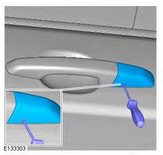
2. NOTE: 3-door illustration shown, 5-door is similar.
Torque: 1.7 Nm
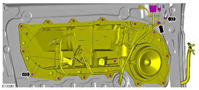
3.

4.

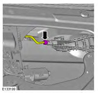
5. NOTE: Loosen the bolt, but do not fully remove.
Torque: 4.1 Nm
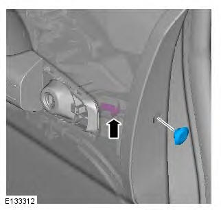
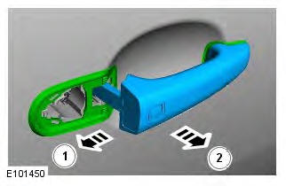
6.
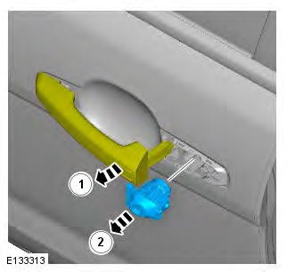
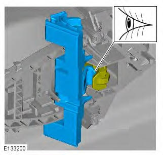
7. NOTE: RH illustration shown, LH is similar.

Installation
1. To install, reverse the removal procedure.
Exterior Rear Door Handle
Removal
NOTES:
Removal steps in this procedure may contain installation details.
Make sure the door window glass is in the fully closed position.
1. Refer to: Rear Door Trim Panel (501-05 Interior Trim and Ornamentation, Removal and Installation).
2. Torque: 1.7 Nm
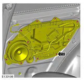
3.
4. NOTE: Remove the screw sufficiently, only to release the component.
Torque: 4.1 Nm
5. NOTE: Some variation in the illustrations may occur, but the essential information is always correct.
Installation
1. To install, reverse the removal procedure.
Door Lock Cylinder
Removal
NOTES:
Removal steps in this procedure may contain installation details.
This procedure is for removal and installation of the door lock cylinder only. The ignition lock and door lock cylinders are replaced in sets.
1.
2. NOTE: Loosen the bolt, but do not fully remove.
Torque: 4.1 Nm

3.

Installation
1. To install, reverse the removal procedure.
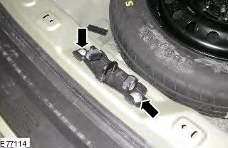
Liftgate Striker Adjustment
NOTE: Some variation in the illustrations may occur, but the essential information is always correct.
1. Check for an equal gap and alignment to the adjacent panels. If incorrect, follow the adjust procedure below.
2. Remove the spare wheel cover.
3. Remove the loadspace scuff plate.
4. Loosen the 2 liftgate striker bolts.
5. Close the liftgate and check for an equal gap and alignment to the adjacent panels.
6. Open the liftgate and tighten the liftgate striker bolts.
Torque: 25 Nm
7. Install the loadspace scuff plate.
8. Install the spare wheel cover.
9. Check the operation of the power tailgate (if fitted) using the power tailgate closing switch. Improper adjustment of the striker can prevent the tailgate from closing.
READ NEXT:
 Wipers and Washers - Component Location, System Operation and Component
Description
Wipers and Washers - Component Location, System Operation and Component
Description
Component Location
COMPONENT LOCATION - SHEET 1 OF 2
Central Junction Box (CJB)
Integrated Control Panel (ICP)
Rain/Light sensor (if fitted)
Right tailgate actuator (upper)
Rear wiper motor
Le
Wipers and Washers - Removal and Installation
Windshield Wiper Motor
Removal
NOTE: Removal steps in this procedure may contain installation details.
1. Refer to: Plenum Chamber (412-01 Climate Control, Removal and
Installation).
2. NOTE: LHD illu
SEE MORE:
System
- Button feedback: Soft key confirmation
tone on or off.
- Clock adjust: Select 12 or 24 hour clock.
Set current time. Select Date to change the
date, or to alter the date format.
Select Set, to store new settings.
Note: The clock can also be adjusted from
the touch screen time display.
- Ho
Voice
- Command list: View the categories and the
acceptable voice commands.
Select an Information button to view
alternative function commands.
- Voicetags: View the categories. Select a
category to manage the voicetags for the
chosen system. See 140, VOICETAGS.
- Operating guide: View brief Voice
