Range Rover Evoque: Wipers and Washers - Component Location, System Operation and Component Description
Component Location
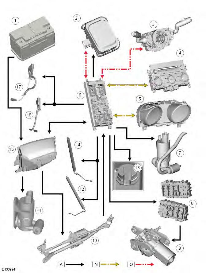
COMPONENT LOCATION - SHEET 1 OF 2
- Central Junction Box (CJB)
- Integrated Control Panel (ICP)
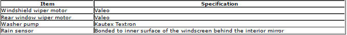
- Rain/Light sensor (if fitted)
- Right tailgate actuator (upper)
- Rear wiper motor
- Left tailgate actuator (upper)
- Rear Junction Box (RJB)
- Wiper control switch
- Instrument Cluster (IC)
- Windshield wiper linkage
- Battery
- Battery Junction Box (BJB)
- Headlamp washer jets
- Left windshield washer jet (heated)
- Windshield washer reservoir
- Right windshield washer jet (heated)
COMPONENT LOCATION - SHEET 2 OF 2
- Washer pump (front/rear)
- Washer pump (headlamp)
- Washer fluid level sensor
OVERVIEW
Windshield wiper and washer operation is controlled by the CJB (central junction box) in response to driver input and if fitted, signals from the rain/light sensor. The front wipers have 4 operational states:
- Flick wipe
- Intermittent/Auto (vehicles without/with rain/light sensor fitted)
- Slow wipe
- Fast wipe.
The 'Auto' function requires an input from the rain/light sensor. The rain/light sensor is mounted on the inner surface of the windshield and transmits an infra-red signal to determine the amount of water on the outer surface of the windshield. A value is then transmitted to the CJB over the LIN (local interconnect network) bus.
The CJB also controls operation of the headlamp wash function.
The rear window wiper system operates independently of the windshield wiper system and is controlled by the CJB on receipt of LIN bus messages from the wiper control switch.
NOTE: The windshield and rear window washers utilize the same pump meaning only 1 wash function, either front or rear, can be performed at any one time.
System Operation and Component Description
Control Diagram
NOTE: A = Hardwired; N = Medium speed CAN (controller area network) bus; O = LIN (local interconnect network) bus
- Battery
- Rain/Light sensor (if fitted)
- Wiper control switch
- Integrated Control Panel (ICP)
- Instrument Cluster (IC)
- Central Junction Box (CJB)
- Windshield and rear window washer pump
- Rear Junction Box (RJB)
- Rear window wiper motor
- Windshield wiper motor
- Headlamp wash pump
- Left tailgate actuator (upper)
- Low level wash fluid sensor
- Right tailgate actuator (upper)
- Battery Junction Box (BJB)
- Left windshield washer jet (heated)
- Right windshield washer jet (heated)
System Operation
The wiper and washer system can operate in a number of different ways when the vehicle is in power mode 4 through 8.
Requests from the wiper control switch are transmitted over the LIN bus to the CJB (central junction box), which is the main controller for the system.
Windshield Wiper Slow Wipe
On receiving a request for slow windshield wiper operation the CJB will energize relay 10 in the BJB (battery junction box).
When energized, relay 10 provides a feed to the switch contacts of relay 9, which is also located in the CJB. Relay 9 is the fast/slow wipe relay. When slow wipe has been requested relay 9 remains de-energized, allowing a feed to flow across the relay switch contacts to the windshield wiper motor slow speed brush contacts.
Windshield Wiper Fast Wipe
On receiving a request for fast windshield wiper operation the CJB will energize relay 10 and relay 9 in the BJB. When energized, relay 10 provides a feed to the switch contacts of relay 9. The energized relay 9 provides a feed to the windshield wiper motor fast speed brush contacts.
Windshield Wiper Intermittent Wipe
On receiving a request for intermittent windshield wiper operation, the CJB will energize relay 10 in the BJB to operate the wipers at slow speed. Software contained within the CJB interprets the time delay requested and controls operation of relay 10 accordingly.
The intermittent wiper setting broadcast on the LIN bus to the CJB equates to the following time delays.
The table below is dependent on configuration / vehicle speed (refer to FAD (Functional Area Description) )
In the event of a LIN bus failure between the CJB and the wiper control switch, the CJB will default to 'Limp Home' mode (see below).
Windshield Wiper Automatic Wipe
On receiving a request for automatic windshield wiper operation, the CJB interprets LIN bus messages received from the rain/light sensor. The rain/light sensor provides LIN bus messages with values ranging from 0 to 7. A signal value of 0 is interpreted by the CJB as there being no water on the windshield.
A signal value from 1 to 6 is interpreted by the CJB as there being a small amount of water hitting the windshield. In this instance, the CJB initiates a slow wipe routine as detailed in the 'Windshield Wiper Slow Wipe' section above.
A signal value from 7 is interpreted by the CJB as there being a large amount of water hitting the windshield. In this instance, the CJB initiates a fast wipe routine as detailed in the 'Windshield Wiper Fast Wipe' section above.
Rain/Light sensor sensitivity can be adjusted by turning the rotary control on the wiper control switch to the required position. Six different sensitivity settings are available, which are broadcast over the LIN bus to the CJB.
NOTE: The CJB will only change a fast wipe routine to a slow wipe routine if the rain sensor value is lower than 7.
Windshield Wiper Flick Wipe
On receiving a request for flick wipe operation the CJB will operate the windshield wipers as described in the 'Slow Wipe' section above until the request is removed.
Windshield Wiper Park
The windshield wiper park switch is integral with the windshield wiper motor. The park switch ensures the windshield wipers return to the park position if the windshield wiper request is cancelled mid-stroke.
The CJB is connected to one side of the park switch. The park switch contacts are open when the wipers are in any position except the park position. While the switch contacts are open, the CJB continues to energize relays 10 and 9 in the BJB, even if a LIN bus signal has been received from the requested the wipers are stopped.
When the wipers reach the park position, the park switch contacts close and a ground path is created. When the CJB registers this ground path its software logic determines the wipers are in the park position and de-energizes relays 10 and 9 in the BJB.
Windshield Wiper Limp Home Mode
In the event of a LIN bus failure between the CJB and the wiper control switch when the windshield wipers are active, the CJB will enter limp home mode. In limp home mode, the CJB will only power the windshield wipers at slow speed.
Windshield Wiper Service Position
The windshield wipers can be parked on the windshield to aid the fitment of new wiper blades. For more information, refer to the 'Owner's Handbook'.
Rear Window Wiper
On receiving a request for rear window wiper operation the CJB will energize the rear wiper relay in the RJB (rear junction box). When energized, the relay provides a feed to the rear window wiper motor. The rear window wiper operates intermittently, with a delay between wipes of approximately 6 seconds. The CJB controls operation of the relay, and consequently rear window wiper motor operation, accordingly.
The CJB also provides a feed to the rear window wiper motor park switch. The park switch is integral with the rear window wiper motor and ensures the wiper returns to the park position if the rear wiper request is cancelled mid-stroke. The park switch contacts are closed when the rear wiper is in any position except the park position. This allows the CJB to return the rear wiper to the park position when the relay is de-energized.
The CJB will also power the rear window wiper motor if reverse gear is selected while the windshield wiper function is active. On vehicles fitted with an automatic transmission, the reverse gear signal originates in the TCM (transmission control module). The TCM broadcasts a reverse gear signal over the high speed CAN bus to the CJB, which responds by operating the rear wiper.
On vehicles fitted with a manual transmission, the reverse gear signal originates at the reverse gear switch. The reverse gear switch is hardwired to the CJB.
Windshield Washers
On receiving a request for windshield washer operation, the CJB will energize the front washer control relay. This allows a battery voltage feed to flow to the washer pump. A ground path for the pump is provided by the de-energized rear washer control relay. Both washer control relays are integral with the CJB.
When windshield washer operation is requested, the windshield washers will operate. The CJB will delay wiper operation for 100 ms after the washer switch is pressed. If the switch is pressed for less than 100 ms, the CJB will not operate the wipers.
The CJB will power the windshield wipers for as long as washer operation is requested, although the washers will time out after 10 seconds. After the washer switch has been released, the CJB will operate the windshield wipers through 2 more wipe cycles.
Rear Window Washer
On receiving a request for rear window washer operation the CJB will energize the rear washer control relay. This allows a battery voltage feed to flow to the washer pump. A ground path for the pump is provided by the de-energized front washer control relay. Reversing the polarity of the pump (see 'Windshield Washers' above) allows washer fluid to be directed to the rear window washer jet rather than the windshield washer jets. The rear window washer jet is incorporated into the rear spoiler.
The rear window washer will operate for up to 10 seconds if continuously requested. When rear window washer operation is requested, the rear window wiper will operate continuously until the switch is released. After the switch has been released, or following 10 seconds of continuous operation, the CJB will operate the rear window wiper through 2 or 3 more wipe cycles.
Headlamp Washers
When the vehicle enters from ignition mode 4 (accessory) to 7 (engine running), the first windshield wash request, greater than 100 ms, will operate a headlamp power wash sequence. The CJB will then start a 10 minute timer. If 5 requests for windshield washer operation are made within this 10 minute window, the CJB will power the headlamp washers upon receiving the fifth request. When this occurs, the 10 minute timer is reset to 0.
If the CJB receives no windshield washer requests during a 10 minute window, the headlamp washers will operate on the first request received after the 10 minute window has elapsed. Again, once the headlamp washers have been operational, the CJB resets the timer to 0.
The headlamp washers will only operate when the headlamps are on. The CJB receives a 'lights on' signal from the light control module over the LIN bus.
When headlamp washer operation is required, the CJB energizes relay 8 in the BJB, allowing a battery voltage feed to power the headlamp washer pump. A ground path for the washer pump is provided by the de-energized relay 11, which is also located in the BJB. This sequence of events provides washer fluid to the headlamp 1 washer jets.
After this sequence the power supply to the pump is reversed. The CJB does this by de-energizing relay 8 and energizing relay 11. This allows the pump to provide washer fluid to the headlamp 2 washer jets. The sequence of events runs as follows:
- Power to headlamp 1 washer - 1100 ms
- Delay to power headlamp 2 washer - 100 ms
- Power to headlamp 2 washer - 1100 ms
- Delay (soak time) to power 1 headlamp washer - 100 ms
- Power to 1 headlamp washer - 1100 ms
- Delay to power 2 headlamp washer - 10 ms
- Power to 2 headlamp washer - 1100 ms
If there is less than 1 liter (0.26 US gallon) of washer fluid in the washer fluid reservoir, the CJB will suspend headlamp washer operation. The fluid level switch is hardwired to the CJB, which also transmits a low fluid signal to the IC over the medium speed CAN bus.
Component Description
WINDSHIELD WIPER MOTOR
- Windshield wiper motor
- Electrical connector
The windshield wiper motor drives a gear wheel via a worm drive attached to the motor spindle. The gear wheel has a central spigot which provides the attachment point for the motor crank. The motor crank attaches directly to the wiper linkage link rods and is secured by a single nut. The motor assembly and wiper linkage are a single component and must be removed or replaced as such.
The motor assembly is connected to the vehicle harness by a 4 pin electrical connector. The electrical connector provides 2 battery voltage feeds from the BJB, a wiper park feed from the CJB, and a ground path for the motor assembly.
WINDSHIELD WIPER LINKAGE
- Right pivot housing
- Right link rod
- Windshield wiper motor
- Left link rod
- Left pivot assembly
- Left crank
- Main tube
- Right crank
The windshield wiper linkage comprises a main tube with pivot housing at each end. The windshield wiper motor is mounted centrally on the main tube and acts directly on a pair of link rods. The link rods convert the rotary motion of the motor into a linear, reciprocating motion.
The link rods are connected to the main tube via a crank at each end. The cranks convert the linear, reciprocating motion of the link rods into a rotary, reciprocating motion of the pivots. This translates to a reciprocating motion of the wiper blades across the windshield.
The windshield wiper linkage and motor assembly are a single component and must be removed or replaced as such.
RAIN/LIGHT SENSOR
The rain/light sensor is located behind the interior mirror trim casing and sits in a bracket which is bonded to the inner surface of the windshield. The sensor contains a number of transmitter and receiver diodes which emit and receive infrared light. By comparing the received light signal against the known transmitted light signal, the rain/light sensor can determine the amount of water on the outer surface of the windshield.
NOTE: A = Clean and dry windshield; B = Wet and dirty windshield
- Windshield outer surface
- Optical element
- Transmitter diodes (100% light transmitted)
- Rain/Light sensor
- Receiver diodes (100% light received)
- Water droplets/film
- Receiver diodes (less than 100% light received)
- Lost light
NOTE: The rain/light sensor also contains a light sensor. The light sensor is used to control operation of the automatic headlamps function.
The rain/light sensor is connected to the vehicle harness by a 3 pin electrical connector. The electrical connector provides a power feed from the CJB, a LIN bus connection to the CJB and a ground path.
REAR WINDOW WIPER MOTOR
- Motor
- Spindle
- Electrical connector
The single speed rear window wiper motor is mounted on the outer surface of the tailgate and is secured by 3 bolts, then covered by a plastic cover. Rubber bushes isolate the motor assembly from the body to help reduce the transmission of motor operating noise to the tailgate. The motor is located on a worm drive mechanism, which converts the rotary motion of the motor output spindle into the required arc for the rear wiper blade.
A 3 pin electrical connector is used to connect the rear window wiper motor to the vehicle harness. The electrical connector provides a power feed to the motor from the RJB, a wiper park feed from the CJB, and a ground path.
The RJB contains the rear window wiper relay. The operation of the relay is controlled by the CJB, which provides feed and ground paths according to logic contained within its software.
Wipers and Washers
Capacities

General Specification
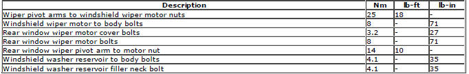
Torque Specifications
READ NEXT:
 Wipers and Washers - Removal and Installation
Windshield Wiper Motor
Removal
NOTE: Removal steps in this procedure may contain installation details.
1. Refer to: Plenum Chamber (412-01 Climate Control, Removal and
Installation).
2. NOTE: LHD illu
Bumpers
Front Bumper Cover
Removal
NOTE: Removal steps in this procedure may contain installation details.
1.
2.
3. WARNING: Make sure to support the vehicle with axle stands.
Raise and support the vehicle.
Safety Belt System
Safety Belt System
Diagnosis and Testing
Principle of Operation
For a detailed description of the seatbelt system and operation, refer to the
relevant description and operation section of
the worksho
SEE MORE:
Important information
The information contained in this handbook covers all vehicle derivatives and
optional equipment,
some of which may not be fitted to your vehicle. Due to printing cycles, this
handbook may include
descriptions of options before they become generally available.
The vehicle options, hardware an
Symbols used in this handbook
Safety warnings indicate either a procedure which must be followed
precisely, or
information that should be considered with great care, in order to avoid the
possibility
of personal injury.
Cautions indicate either a procedure which must be followed precisely, or
information that
should
