Range Rover Evoque: Air Bag Supplemental Restraint System (SRS)
Component Location
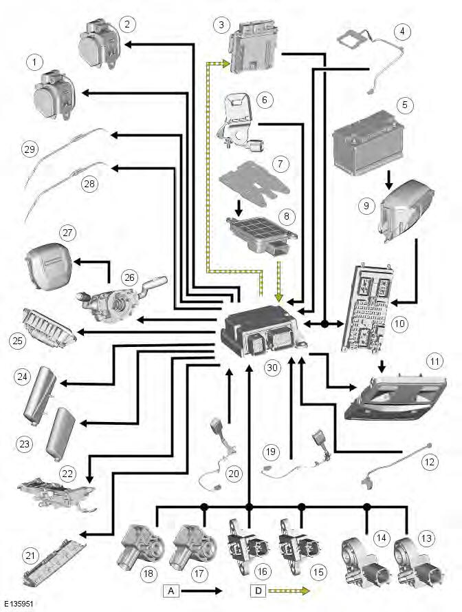
COMPONENT LOCATION SHEET 1 OF 2
- Battery
- ECM (engine control module)
- CJB (central junction box)
- Passenger air bag
- Overhead console
- RCM (restraints control module)
- Driver air bag
- Driver lower air bag
- Clockspring
- Adaptive steering column
- BJB (battery junction box)
COMPONENT LOCATION SHEET 2 OF 2
- Passenger buckle switch
- RH (right-hand) door impact sensor
- Passenger safety belt tensioner
- Passenger side air bag
- RH side air curtain
- RH rear side impact sensor
- LH (left-hand) rear side impact sensor
- Driver side air bag
- Driver safety belt tensioner
- LH side air curtain
- LH door impact sensor
- Driver buckle switch
- LH front impact sensor
- RH front impact sensor
Overview
OVERVIEW
WARNING: All pyrotechnic devices are dangerous. Before performing any procedures on any pyrotechnic device, read all information contained within the Standard Workshop Practices section of this manual.
The continued development of the SRS (supplemental restraint system) provides an improved overall level of crash protection for vehicle occupants. The system analyzes the occupancy scenario and crash severity before activating the appropriate safety devices to better protect a range of occupants in a variety of crash situations. Benefits of the system include:
- Optimization of the deployment restraint devices and the reduction in potential for air bag induced injuries.
- The significant reduction in passenger air bag deployments; particularly when passenger seats are unoccupied.
There are seven separate air bags, each designed with a specific protection function:
- Driver and front passenger air bags provide head and chest protection for front occupants.
- Driver and front passenger side air bags provide protection against side impact.
- Side air curtains provide protection against head impact and roll-over ejection for both front and rear occupants.
- A driver lower air bag provides protection to the driver's legs from the steering column support structures.
In order to support the SRS requirements, restraint control architecture is used comprising the following systems or components:
- All electronic front and side crash sensing and advanced restraints management.
- Driver air bag with twin stage inflator.
- Passenger air bag with twin stage inflator.
- Depending on market, a front passenger seat:
- occupant classification sensing system, or
- occupant detection sensing system.
- Safety belt buckle pretensioners.
- A seat position sensor on the driver seat.
- Depending on market, a pyrotechnic actuator fitted to the steering column to provide increased energy absorption.
System Operation and Component Description
Control Diagram
NOTE: A = Hardwired; D = High speed CAN (controller area network) bus.
- Driver safety belt tensioner
- Passenger safety belt tensioner
- ECM (engine control module)
- Belt minder sensor (markets except NAS and Australia)
- Battery
- Safety belt tension sensor
- Occupancy sensor (NAS markets)
- Occupancy sensor module
- BJB (battery junction box)
- CJB (central junction box)
- Overhead console
- Driver seat track sensor
- RH (right-hand) front impact sensor
- LH (left-hand) front impact sensor
- RH front door impact sensor
- LH front door impact sensor
- RH rear side impact sensor
- LH rear side impact sensor
- Passenger buckle switch / safety belt pretensioner
- Driver buckle switch / safety belt pretensioner
- Driver lower air bag
- Adaptive steering column
- RH front side air bag
- LH front side air bag
- Passenger air bag
- Clockspring
- Driver air bag
- RH side air curtain
- LH side air curtain
- RCM (restraints control module)
System Operation
Crash Sensing
Impact sensor
The impact sensors are installed in the front and both sides of the vehicle. When the ignition is switched on the RCM, supplies power to the impact sensors which perform a self-test. After satisfactory self-test, the impact sensors continually output 'digital acceleration' messages to the restraints control module. The use of multiple impact sensors provide shorter air bag trigger times through faster detection of lateral and longitudinal acceleration and also improves detection accuracy.
Each impact sensor incorporates an accelerometer and a microchip powered by a feed from the restraints control module.
Acceleration is evaluated by the microchip and transmitted to the restraints control module, which then makes the decision on whether or not to activate the air bags and pretensioners.
If a fault is detected the relevant impact sensor sends a fault message, instead of the digital acceleration message, to the restraints control module. The RCM then stores a related fault code and illuminates the air bag warning indicator. Faults can be retrieved by the Land Rover approved diagnostic system from the RCM via the high-speed CAN.
Occupant Monitoring
There are two types of occupant monitoring systems fitted to vehicles:
- NAS markets, have an Occupant Classification Sensing System.
- Markets except NAS and Australia, have an Occupant Detection Sensing System.
1. Occupant Classification Sensing System
- Occupancy sensor
- Occupancy sensor module
- Safety belt tension sensor
In NAS markets where safety belt use is infrequent, additional technology is used to classify the occupant of the front passenger seat. The occupant classification sensing system provides seat load data to the RCM.
The occupant classification system consists of:
- A pressure pad, installed under the cushion of the front passenger seat, which is connected to a pressure sensor.
- A safety belt tension sensor, integrated into the anchor point of the front passenger safety belt.
- An occupant classification module, installed under the front passenger seat.
The pressure pad is a silicone filled bladder. Any load on the pressure pad is detected by the pressure sensor. The safety belt tension sensor is a strain gauge which measures the load applied by the safety belt anchor to the anchor bolt. The sensor is located in the lower safety belt anchor point.
The occupancy sensor responds to weight changes on the passenger seat and provides an appropriate signal to the occupancy sensor module. In addition, the belt tension sensor provides a separate input to the occupancy sensor module.
The module processes the input signals received from the sensors and forwards an appropriate signal to the RCM on the high-speed CAN.
The RCM monitors and processes the data from these and several other sensors, before making an air bag deployment decision. The system is designed to take account of several variables in addition to weight, including: inclination of the vehicle and exact position and structure of the weight on the seat.
This protects against inadvertent air bag deployment, for example, if the seat were occupied by an infant in a booster seat, or an unrestrained but very lightweight adult, in both these cases the air bag would be disabled. The occupant classification sensing system forms part of a strategy to control passenger air bag deployment depending on the occupancy scenario.
The occupant classification system has four possible states:
- Seat Empty: the passenger air bag, passenger-side air bag and passenger safety belt buckle and pretensioner operation is disabled; the passenger air bag deactivation indicator is not illuminated.
- Occupied Inhibit: when the seat is occupied by a small person, the passenger air bag, passenger-side air bag and passenger safety belt buckle and pretensioner operation is disabled; the passenger air bag deactivation indicator is illuminated.
- Occupied Allow: when the seat is occupied by a large person; the
passenger air bag and passenger-side air bag
operation is enabled, the passenger air bag deactivation indicator is not
illuminated. Passenger safety belt and
pretensioner operation status depends on the safety belt buckle status:
- active for buckled,
- inactive for unbuckled.
- Error: if a system fault is detected; the passenger air bag is enabled
to deploy at 'stage-1' only, refer to Air Bag
Dual Stage Inflators below. Passenger-side air bag operation is also
enabled; the passenger air bag deactivation
indicator is not illuminated. Passenger safety belt and pretensioner
operation status depends on the safety belt
buckle status:
- active for buckled,
- inactive for unbuckled.
Occupancy Sensor Module
The occupancy sensor module is installed on the underside of the front passenger seat. The module supplies a power feed to the occupancy sensor and monitors the return voltage to determine if the seat is occupied or not. The result is transmitted to the RCM on the high speed CAN. The occupancy sensor module also monitors for short and open circuits in the occupancy sensor. If it detects a fault, the occupancy sensor module transmits a fault message to the RCM.
Safety Belt Tension Sensor
The safety belt tension sensor is a strain-gauge type, encapsulated within the passenger safety belt anchor. The sensor converts the force applied to the safety belt into an electrical signal. In the event that a child-seat is installed onto the front passenger seat, the force applied to the passenger safety belt is reflected by the output signal from the sensor, which provides data to supplement that received from the occupancy sensor. The occupancy sensor module processes the input data and makes it available to the restraints control module, which then makes the necessary adjustments in respect of passenger air bag deployment.
2. Occupant Detection Sensing System
The belt-minder sensor and a safety belt buckle switch are used to warn the driver if the front passenger seat is occupied without the safety belt being engaged.
Belt Minder Sensor
The occupancy sensor is installed in the cushion of the front passenger seat between the foam padding and the cover. The sensor consists of a foil contact circuit, embedded in a plastic sheet. Weight on the sensor reduces the resistance of the circuit.
The safety belt buckle switch provides an output signal in response to the insertion of the safety belt tongue into the buckle. The output signal from the switch is used by the RCM to determine whether the front seat occupants are correctly restrained. The switch signal is used in conjunction with the belt minder sensor to ensure that air bag and safety belt deployment only occurs when the seat is occupied.
Component Description
Driver Position Sensing System
Seat Position Sensor
- Seat position sensor
The seat position sensor, a 'Hall effect' type, is fitted to the underside of the driver's seat. The sensor is actuated by the target bracket attached to the seat slide. The disturbance caused when the target bracket passes the sensor creates an output signal for the RCM. On receipt of this signal, which indicates when the seat is forward of a defined point in its travel, the RCM disables the second stage output of the driver air bag; refer to air bags section.
Control and Processing
Restraints Control Module
Internally, the RCM has two areas that determine which elements of the restraint system are to be deployed:
Area 1 - Crash severity evaluation:
The first area evaluates crash severity by using data from the module's internal accelerometer, the front crash sensor and the safety-belt buckle sensor. Based on this data, the RCM decides which level of air bag deployment is required and forwards the information to the second area, the deployment handler.
Area 2 - Deployment handler:
The status of the seat position sensor, occupant classification sensing system and safety-belt buckle sensors are examined before a decision is made about which restraints should finally be deployed. For instance, if the occupant classification sensing system indicates that the passenger seat is empty, then no restraint deployment will take place on the passenger side, even if full deployment takes place for the driver.
An energy reserve in the RCM ensures there is always a minimum of 150 milliseconds of stored energy available if the power supply from the ignition switch is disrupted during a crash. The stored energy is sufficient to produce firing signals for the driver air bag, the passenger air bag and the safety belt pretensioners.
When the ignition is switched on the RCM performs cyclical monitoring of the system. If a fault is detected, the RCM stores a related fault code and sends the signal to illuminate the air bag warning indicator. The faults can be retrieved by the Land Rover approved diagnostic system. If a fault that could cause a false fire signal is detected, the RCM disables the respective firing circuit, and keeps it disabled during a crash event.
Air Bags
Hybrid Inflator Technology
Air bags feature hybrid inflators, rather than the previously used solid pyrotechnic gas generators which use an explosion to generate the air bag charge directly. Hybrid inflators use a self-contained pyrotechnic device to heat a cylinder of compressed inert gas within the inflator. Above a calibrated pressure, this cylinder bursts and the gas is released into the fabric bag.
The benefits of hybrid inflators are cooler gas, hence lower bag surface temperatures, and the elimination of post-deployment effluent associated with solid pyrotechnic generators.
Dual Stage Inflators
Both the driver air bag and passenger air bag feature dual-stage inflators. Each air bag employs two separate inflators, fitted with independent squibs connected to the air bag. This allows air bag size, pressure and rate of rise in pressure to be optimized to suit the vehicle's structural characteristics as well as the severity of the actual impact.
The RCM monitors the severity of the collision, safety belt tension and proximity of the driver's seat to the steering wheel in order to determine the air bag deployment strategy:
- At relatively low speeds, or when smaller occupants are seated close to the steering wheel only the 'stage 1' inflator deploys; this inflates the air bag to about 70% of its capacity.
- At higher speed impacts both 'stage 1' and after a pre-set interval, 'stage 2' inflator deploys to achieve maximum air bag volume, unless the driver is dangerously close to the steering wheel.
Driver Air Bag
The driver air bag has a two stage inflator, with separate electrical connectors for each stage. Lines molded into the inner surface of the driver air bag cover, provide weak points that split open in a controlled manner when the driver air bag deploys.
Driver Lower Air Bag
- Single stage inflator
The lower driver air bag has a single stage inflator. The module has an integral door and is attached to the lower trim panel beneath the steering column. Weak points in the door break in a control manner to allow the door to hinge downward when the air bag deploys.
Passenger Air Bag
- Stage one - 70% air bag volume
- Stage two - full air bag volume
The top of the passenger air bag is attached to a re-enforcement lid in the instrument panel. The reinforcement lid incorporates a single door that opens, splitting the instrument panel covering, when the air bag deploys. The air bag has a two stage inflator, with separate electrical connectors for each stage.
Passenger Air Bag Deactivation Indicator
- Passenger air bag deactivation indicator
When the passenger air bag is deactivated, the RCM disables the passenger air bag and if the front passenger seat is occupied, illuminates the passenger air bag deactivation indicator.
Side Air Bags
A side air bag is attached to the outside of each front seat backrest frame, under the backrest cover.
The side air bags are handed and each consists of soft cover / wrapper that contains the folded air bag and the inflator. A cable connects the igniter of the inflator to a connector in the main seat harness connector block located under the seat cushion. When the air bag deploys it fills within a deployment chute (integral to the seat trim) and splits open the airbag deployment seam in the seat backrest cover.
Side Air Curtains
Side air curtains protect against head injuries in a side impact, while also helping to ensure unrestrained occupants are not ejected through open or broken windows during a rollover event. The side air curtains are derivatized between the 3 and 5 door vehicles to suit the different B' pillar locations.
A single inflator is mounted behind the B' pillar and unfurls the curtain air bag, filling the cushion to provide head protection cushions for occupants in side-impact and rollover events. Tethers at the front and rear of the curtain ensure the curtain is held taut.
The side air curtain deflation characteristics are deliberately slow to ensure it remains inflated throughout the duration of a vehicle rollover event.
Air Bag Warning Indicator
The air bag warning indicator consists of a red LED (light emitting diode) behind a SRS (supplemental restraint system) graphic in the instrument cluster.
Operation of the air bag warning indicator is controlled by a high speed CAN bus message from the RCM to the instrument cluster. The RCM sends the signal to illuminate the air bag warning indicator if a fault is detected, and for approximately 6 seconds during the bulb check at the beginning of each ignition cycle.
Clockspring
The clockspring is installed on the steering column to provide the electrical interface between the vehicle's fixed wiring harness and the steering wheel. The clockspring provides connections for the driver air bag, horn and steering wheel switch packs, plus a high current feed to the heated wheel.
Safety Belt Pretensioners
The pretensioners are located in the retractors. Each pretensioner tightens the front safety belts during a collision to ensure the occupants are securely held in their seats.
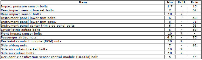
Supplemental Restraint System
Torque Specifications
READ NEXT:
 Restraints Control Module (RCM)
Removal
NOTES:
The RCM must be replaced after every time any SRS component has been
deployed.
Removal steps in this procedure may contain installation details.
1. Make the SRS system safe.
Refer to
Side Air Bag Module
Removal
NOTE: Removal steps in this procedure may contain installation details.
All vehicles
1. Make the SRS system safe.
Refer to: Standard Workshop Practices (100-00 General Information,
Descripti
Side Air Curtain Module
Removal
CAUTION: Do not allow the side air curtain module to twist. Failure to
follow this instruction may result in damage to
the component.
NOTES:
Removal steps in this procedure may contain instal
SEE MORE:
Important information
The information contained in this handbook covers all vehicle derivatives and
optional equipment,
some of which may not be fitted to your vehicle. Due to printing cycles, this
handbook may include
descriptions of options before they become generally available.
The vehicle options, hardware an
Symbols used in this handbook
Safety warnings indicate either a procedure which must be followed
precisely, or
information that should be considered with great care, in order to avoid the
possibility
of personal injury.
Cautions indicate either a procedure which must be followed precisely, or
information that
should
