Range Rover Evoque: Side Air Bag Module
Removal
NOTE: Removal steps in this procedure may contain installation details.
All vehicles
1. Make the SRS system safe.
Refer to: Standard Workshop Practices (100-00 General Information,
Description and Operation).
2. Disconnect the battery ground cable.
Refer to: Specifications (414-01 Battery, Mounting and Cables,
Specifications).
3. Refer to: Front Seat Control Switch (501-10 Seating, Removal and
Installation).
4. Refer to: Front Seat (501-10 Seating, Removal and Installation).
5. NOTE: If equipped.
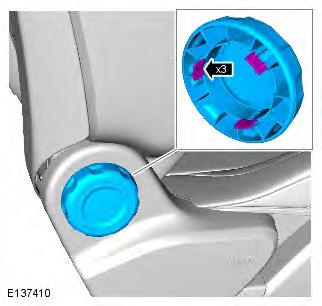
6.
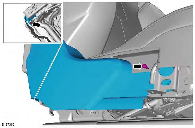
7.
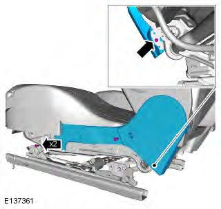
8.
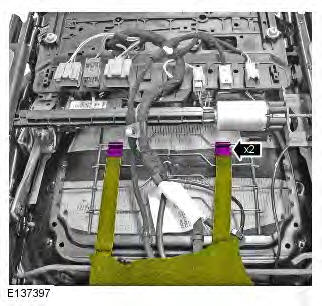
9. NOTE: Release the 2 clips located on the
underside of the front seat.
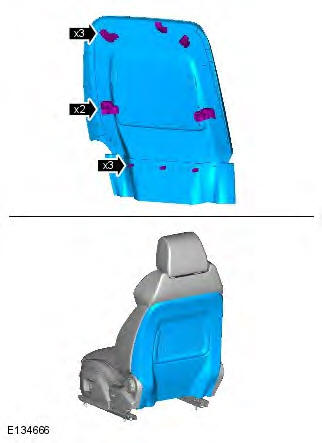
10.
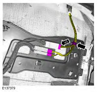
11.
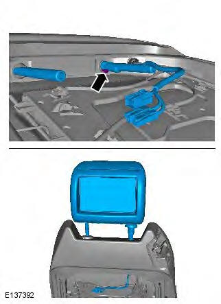
12.
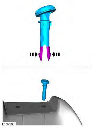
3-door
13.
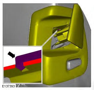
14.
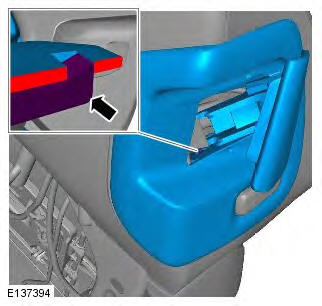
All vehicles
15.
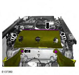
16.
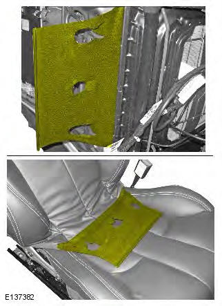
17.
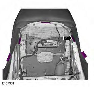
18. WARNING: The SRS electrical connectors are
unique. DO NOT force, or attempt to connect electrical
connectors to the wrong sockets.
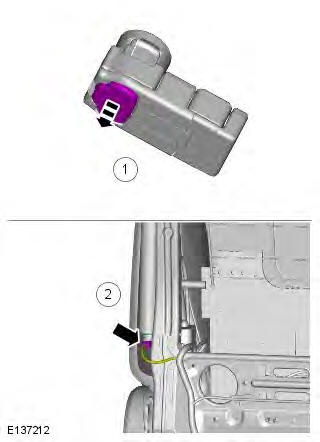
19. WARNING: Make sure that the air bag is correctly
installed in to the fabric chute. Failure to follow this
instruction may result in incorrect operation of the air
bag.
Torque: 7 Nm
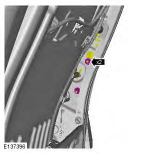
20.
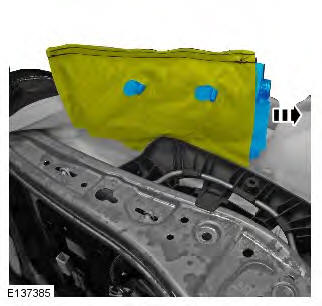
Installation
1. To install, reverse the removal procedure.
READ NEXT:
Removal
CAUTION: Do not allow the side air curtain module to twist. Failure to
follow this instruction may result in damage to
the component.
NOTES:
Removal steps in this procedure may contain instal
Removal
CAUTION: Make sure that the road wheels are in the straight ahead
position.
NOTE: Removal steps in this procedure may contain installation details.
1. Make the SRS system safe.
Refer to: St
Principle of Operation
For a detailed description of the supplemental restraints system and
operation, refer to the relevant Description and
Operation section in the workshop manual. REFER to: (501-2
SEE MORE:
If you are in any doubt
regarding your
ability to carry out the instructions,
contact your Dealer/Approved
Repairer before attempting the repair.
Your vehicle may not be equipped with a spare
tyre. If this is the case, your vehicle will be
fitted with a Land Rover tyre repair kit which
can
Connecting a device
1. USB/iPod sockets.
2. 3.5 mm AUX socket.
3. Rear media USB/iPod socket.
4. Rear media AV sockets.
Connect the device into the appropriate socket.
Note: Use the cable supplied with your media
device to connect to the USB socket.
When an iPod is connected, playback will
© 2011-2026 Copyright www.rrevoque.org


