Range Rover Evoque: Clockspring
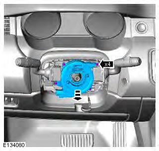
Removal
CAUTION: Make sure that the road wheels are in the straight ahead position.
NOTE: Removal steps in this procedure may contain installation details.
1. Make the SRS system safe.
Refer to: Standard Workshop Practices (100-00 General Information, Description and Operation).
2. Refer to: Steering Wheel (211-04 Steering Column, Removal and Installation).
3.
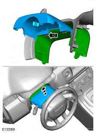
4.
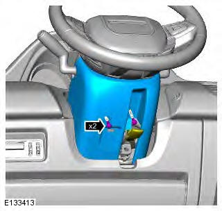
5.
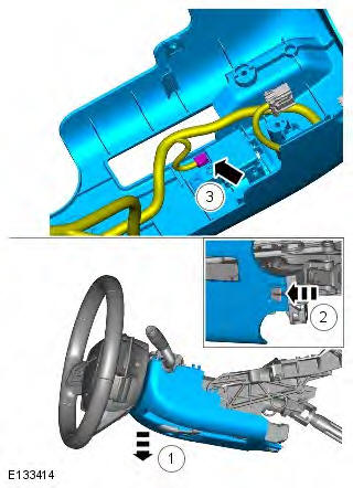
6. CAUTION: Make sure that the clockspring rotor does not rotate. Secure with adhesive tape.
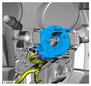
7.
Installation
1. To install, reverse the removal procedure.
2. If a new component is installed, the soft lock stop reset routine should be completed on the power steering system, using the approved diagnostic tool.
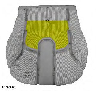
Occupant Detection Sensor
Removal
WARNINGS:
To avoid accidental deployment and possible personal injury, the backup power supply must be depleted before repairing or replacing any air bag supplemental restraint system (SRS) components. To deplete the backup power supply energy, disconnect the battery ground cable and wait one minute. Failure to follow this instruction may result in personal injury.
Never probe the electrical connectors of air bag modules or any other supplemental restraint system component.
Failure to follow this instruction may result in personal injury.
NOTE: Removal steps in this procedure may contain installation details.
All vehicles
1. Disconnect the battery ground cable.
Refer to: Specifications (414-01 Battery, Mounting and Cables, Specifications).
2. Refer to: Front Seat Cushion Cover (501-10 Seating, Removal and Installation).
Vehicles with heated front seats
3.
All vehicles
4.
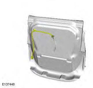
5.
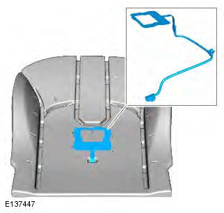
Installation
1. CAUTION: Make sure the component is aligned as shown.
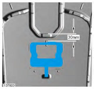
2. CAUTION: Make sure the component is aligned as shown.
3. To install, reverse the removal procedure.
C-Pillar Side Impact Sensor
Removal
NOTES:
Removal steps in this procedure may contain installation details.
3-door illustration shown, 5-door is similar.
All vehicles
1. WARNING: To avoid accidental deployment and possible personal injury, the backup power supply must be depleted before repairing or replacing any air bag supplemental restraint system (SRS) components. To deplete the backup power supply energy, disconnect the battery ground cable and wait one minute. Failure to follow this instruction may result in personal injury.
Refer to: Standard Workshop Practices (100-00 General Information, Description and Operation).
5-door
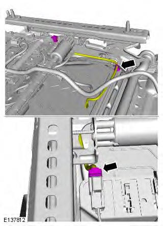
2. Refer to: C-Pillar Lower Trim Panel (501-05 Interior Trim and Ornamentation, Removal and Installation).
3-door
3. Refer to: Rear Quarter Trim Panel (501-05 Interior Trim and Ornamentation, Removal and Installation).
All vehicles
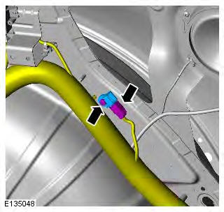
4. Torque: 7 Nm
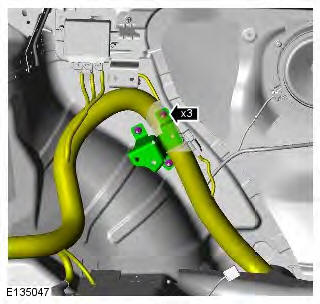
5. Torque: 10 Nm
Installation
1. To install, reverse the removal procedure.
2. If a new component has been installed, configure using Land Rover approved diagnostic equipment.
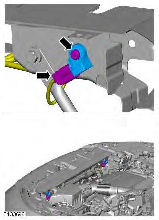
Front Impact Severity Sensor
Removal
NOTE: Removal steps in this procedure may contain installation details.
1. WARNING: To avoid accidental deployment and possible personal injury, the backup power supply must be depleted before repairing or replacing any air bag supplemental restraint system (SRS) components. To deplete the backup power supply energy, disconnect the battery ground cable and wait one minute. Failure to follow this instruction may result in personal injury.
Make the SRS system safe.
Refer to: Standard Workshop Practices (100-00 General Information, Description and Operation).
2. Torque: 10 Nm
Installation
1. To install, reverse the removal procedure.
2. If a new component has been installed, configure using Land Rover approved diagnostic equipment.
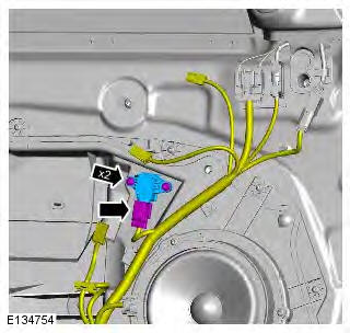
Front Door Side Impact Sensor
Removal
NOTE: Removal steps in this procedure may contain installation details.
1. WARNING: To avoid accidental deployment and possible personal injury, the backup power supply must be depleted before repairing or replacing any air bag supplemental restraint system (SRS) components. To deplete the backup power supply energy, disconnect the battery ground cable and wait one minute. Failure to follow this instruction may result in personal injury.
Refer to: Standard Workshop Practices (100-00 General Information, Description and Operation).
2. Refer to: Front Door Trim Panel (501-05 Interior Trim and Ornamentation, Removal and Installation).
3. Torque: 1.7 Nm
Installation
1. To install, reverse the removal procedure.
2. If a new component has been installed, configure using Land Rover approved diagnostic equipment.
READ NEXT:
 Air Bag and Safety Belt Pretensioner
Supplemental Restraint System (SRS)
Air Bag and Safety Belt Pretensioner
Supplemental Restraint System (SRS)
Principle of Operation
For a detailed description of the supplemental restraints system and
operation, refer to the relevant Description and
Operation section in the workshop manual. REFER to: (501-2
Side Air Bag Module Vehicles With: Sports
Seats
Removal
WARNINGS:
To avoid accidental deployment and possible personal injury, the backup
power supply must be depleted before
repairing or replacing any air bag supplemental restraint system (SRS)
Body Repairs - General Information
General Information
Introduction
The body plays a significant role in the increasing trend of ever more
rapidly changing model variants. The different
customer groups are strongly influenced by the d
SEE MORE:
Important information
The information contained in this handbook covers all vehicle derivatives and
optional equipment,
some of which may not be fitted to your vehicle. Due to printing cycles, this
handbook may include
descriptions of options before they become generally available.
The vehicle options, hardware an
Symbols used in this handbook
Safety warnings indicate either a procedure which must be followed
precisely, or
information that should be considered with great care, in order to avoid the
possibility
of personal injury.
Cautions indicate either a procedure which must be followed precisely, or
information that
should
