Range Rover Evoque: Side Air Bag Module Vehicles With: Sports Seats
Removal
WARNINGS:
To avoid accidental deployment and possible personal injury, the backup power supply must be depleted before repairing or replacing any air bag supplemental restraint system (SRS) components. To deplete the backup power supply energy, disconnect the battery ground cable and wait one minute. Failure to follow this instruction may result in personal injury.
Never probe the electrical connectors of air bag modules or any other supplemental restraint system component.
Failure to follow this instruction may result in personal injury.
NOTES:
Removal steps in this procedure may contain installation details.
Some variation in the illustrations may occur, but the essential information is always correct.
All vehicles
1. Make the SRS system safe.
Refer to: Standard Workshop Practices (100-00 General Information, Description and Operation).
2. Disconnect the battery ground cable.
Refer to: Specifications (414-01 Battery, Mounting and Cables, Specifications).
3. Refer to: Front Seat Control Switch (501-10 Seating, Removal and Installation).
4. Refer to: Front Seat (501-10 Seating, Removal and Installation).
3-door
5.
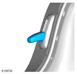
6.
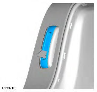
7.
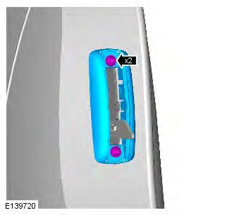
8.
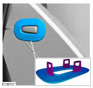
All vehicles
9.
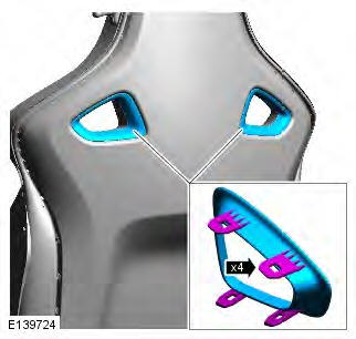
10.
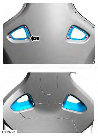
11.
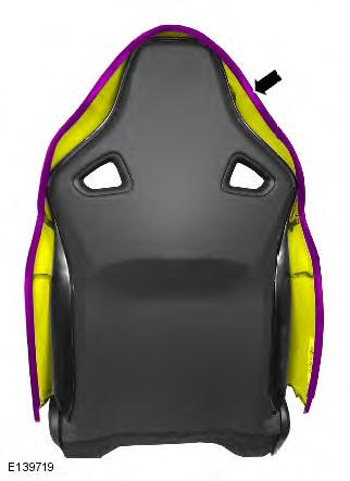
12. NOTE: Note the fitted position of the component prior to removal.
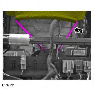
13.
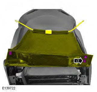
14.
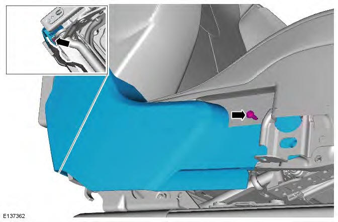
15.
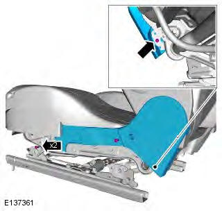
16. CAUTION: Take extra care not to damage the component.
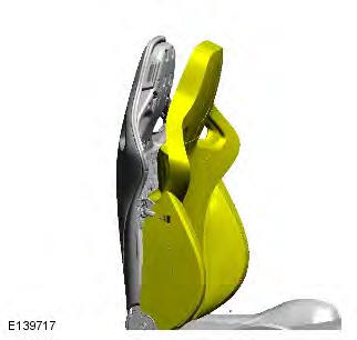
17.
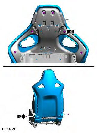
18. WARNING: The SRS electrical connectors are unique. DO NOT force, or attempt to connect electrical connectors to the wrong sockets.
Torque: 7 Nm
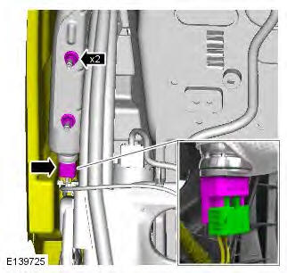
19. WARNING: Make sure that the air bag is correctly installed in to the fabric chute. Failure to follow this instruction may result in incorrect operation of the air bag.
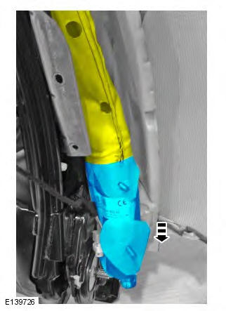
Installation
1. To install, reverse the removal procedure.
Occupant Detection Sensor Vehicles With: Sports Seats
Removal
NOTE: Removal steps in this procedure may contain installation details.
All vehicles
1. Disconnect the battery ground cable.
Refer to: Specifications (414-01 Battery, Mounting and Cables, Specifications).
2. Make the SRS system safe.
Refer to: Standard Workshop Practices (100-00 General Information, Description and Operation).
3. Refer to: Front Seat Cushion Cover - Vehicles With: Sports Seats (501-10 Seating, Removal and Installation).
Vehicles with heated front seats
4.
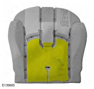
All vehicles
5.
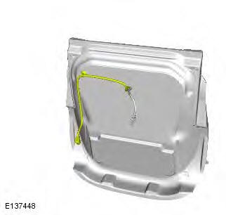
6.
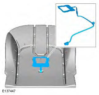
Installation
1. CAUTION: Make sure that the component is aligned and attached as shown.
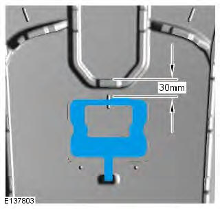
2. CAUTION: Make sure the component is aligned as shown.
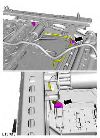
3. To install, reverse the removal procedure.

