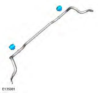
Range Rover Evoque: Front Stabilizer Bar AWD
Removal
CAUTION: Nuts and bolts must be tightened with the weight of the vehicle on the suspension.
NOTES:
Only use clean water as a lubricant for the bushing, if required.
Removal steps in this procedure may contain installation details.
1. WARNING: Make sure to support the vehicle with axle stands. Raise and support the vehicle.
2. Remove the front wheels and tires.
Refer to: Wheel and Tire (204-04 Wheels and Tires, Removal and Installation).
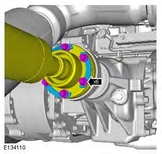
3. CAUTION: Make sure that new bolts are installed.
- Torque: 40 Nm
- Using a suitable tie strap, secure the driveshaft.
4. Refer to: Catalytic Converter (309-00A Exhaust System - GTDi 2.0L Petrol, Removal and Installation).
Refer to: Catalytic Converter - Vehicles Without: Diesel Particulate Filter (DPF) (309-00B Exhaust System - TD4 2.2L Diesel, Removal and Installation).
Refer to: Catalytic Converter - Vehicles With: Diesel Particulate Filter (DPF) (309-00B Exhaust System - TD4 2.2L Diesel, Removal and Installation).
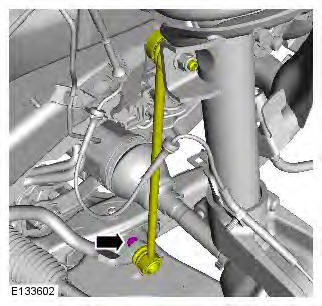
5. WARNING: Make sure that a new nut is installed.
CAUTION: Make sure that the ball joint ball does not rotate.
- Torque: 60 Nm
- Repeat the above step for the other side.
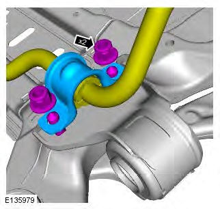
6. WARNING: Make sure that new nuts are installed.
- Torque:
Stage 1: 175 Nm
Stage 2: 175 Nm
- Repeat the above step for the other side.
7. NOTE: Subframe shown removed for clarity.
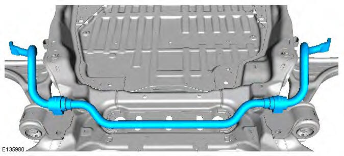
8. Inspect the components and install new if damaged or worn.
Installation
1. To install, reverse the removal procedure.
READ NEXT:
 Front Stabilizer Bar Bushing
Removal
NOTES:
Some variation in the illustrations may occur, but the essential
information is always correct.
Removal steps in this procedure may contain installation details.
1. WARNING: Make sure
Wheel Knuckle
Special Tool(s)
205-754A
Splitter, Ball Joints
205-857
Remover, Halfshaft
JLR-204-804
Lever, Wheel Knuckle
Removal
CAUTIONS:
Nuts and bolts must be tightened with the weight of the vehicle on the
sus
Front Shock Absorber Vehicles Without: Dynamic
Suspension
General Equipment
Suspension Spring Compressor
Vise
Removal
WARNINGS:
Make sure the spring compressor Safe Working Load (SWL) meets or exceeds
the spring rating quoted in the
Specifcations sectio
SEE MORE:
Exterior Front/Rear Door Handle
Exterior Front Door Handle
Removal
NOTES:
Removal steps in this procedure may contain installation details.
Some variation in the illustrations may occur, but the essential information is
always correct.
Make sure the door window glass is in the fully closed position.
1. Refer to: Front Door Tri
Wipers and Washers - Component Location, System Operation and Component
Description
Component Location
COMPONENT LOCATION - SHEET 1 OF 2
Central Junction Box (CJB)
Integrated Control Panel (ICP)
Rain/Light sensor (if fitted)
Right tailgate actuator (upper)
Rear wiper motor
Left tailgate actuator (upper)
Rear Junction Box (RJB)
Wiper control switch
Instrument Cluster (IC)
