Range Rover Evoque: Fuel Charging and Controls - Turbocharger - GTDi 2.0L Petrol
Torque Specifications
Turbocharger
Removal
NOTES:
Some illustrations may show the engine removed for clarity.
Some variation in the illustrations may occur, but the essential information is always correct.
Removal steps in this procedure may contain installation details.
1. Disconnect the battery ground cable.
2. Refer to: Cooling System Draining, Filling and Bleeding (303-03B Engine Cooling - GTDi 2.0L Petrol, General Procedures).
3. Refer to: Engine Cover - GTDi 2.0L Petrol (501-05 Interior Trim and Ornamentation, Removal and Installation).
4. Refer to: Front Subframe (502-00 Uni-Body, Subframe and Mounting System, Removal and Installation).
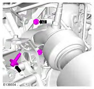
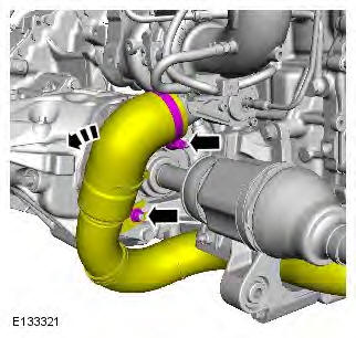
5.
6. Torque:
- Clamp 3.5 Nm
- Bolt 8 Nm
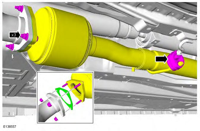
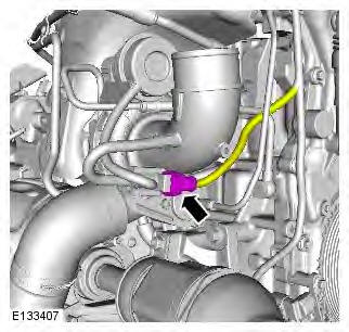
7.
8. Torque:
- M6 10 Nm
- M10 45 Nm
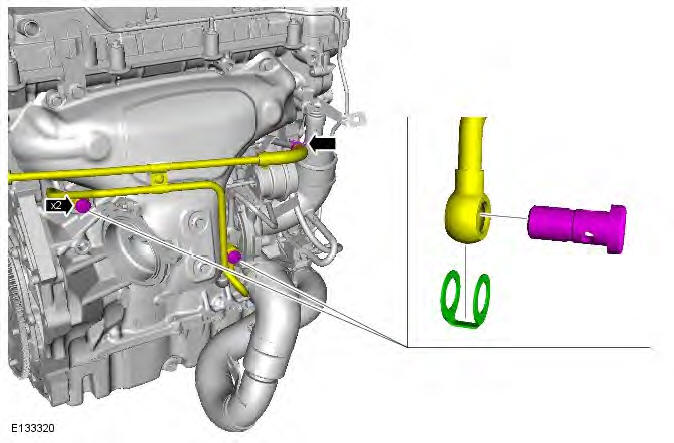
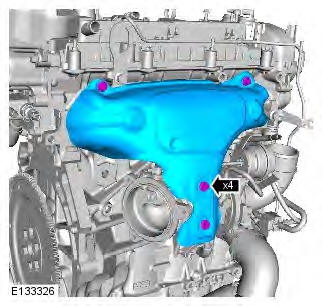
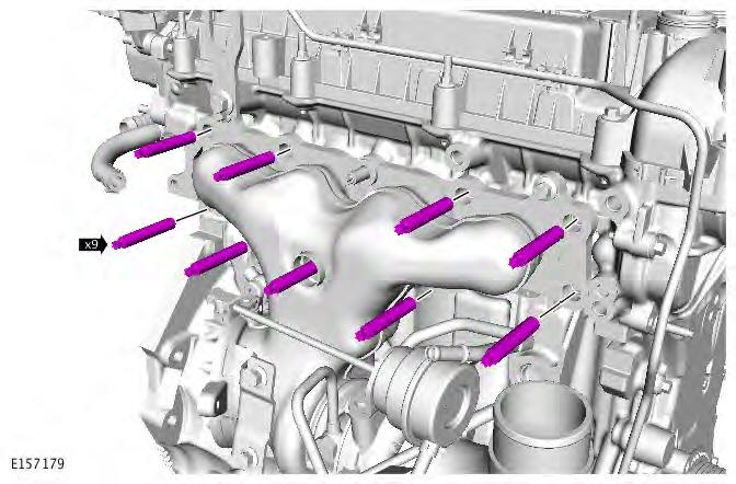
9.
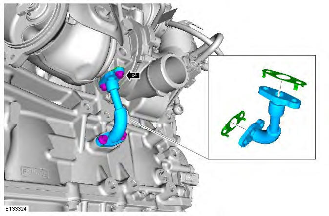
10.
11.
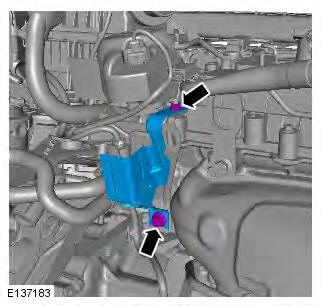
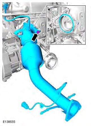
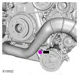
12. CAUTION: Loosen the lower retaining bolt no more than 5 turns (do not remove the retaining bolt).
This will aid installation of the catalytic converter. Torque: 24 Nm
13. NOTE: Secure with cable ties. Torque: 24 Nm
14. Torque: 24 Nm
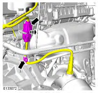
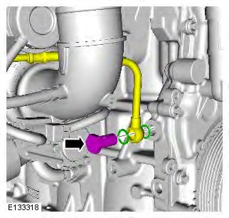
15. CAUTIONS:
Be prepared to collect escaping coolant.
Make sure that new sealing washers are installed.
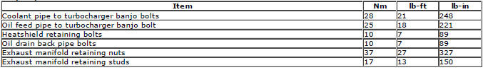
NOTE: Some variation in the illustrations may occur, but the essential information is always correct.
Torque: 28 Nm
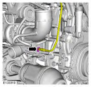
16. Torque: 10 Nm
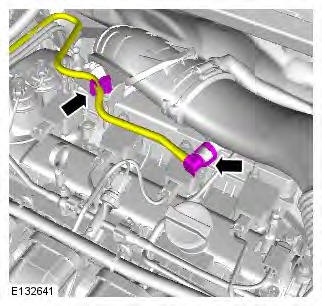
17. WARNING: Be prepared to collect escaping fluids.
Torque: 25 Nm
18.
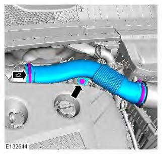
19. Torque: 25 Nm
20. Torque: 25 Nm
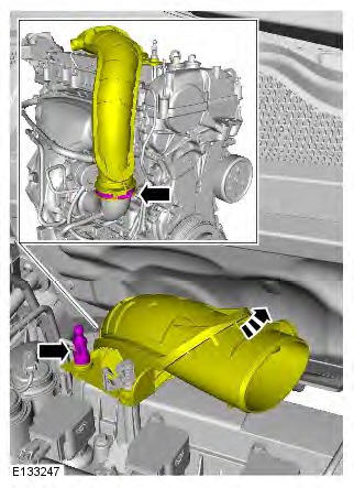
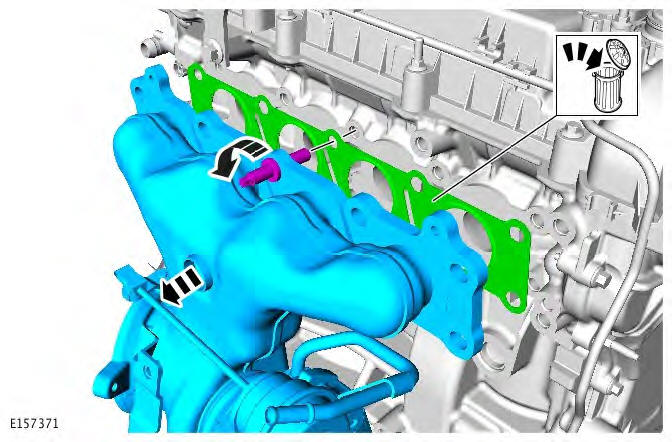
21. CAUTIONS:
Make sure that the gasket is correctly located.
Make sure that a new component is installed.
Be prepared to collect escaping fluids.
NOTE: Install new gaskets.
Torque: 10 Nm
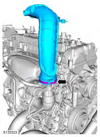
22.
23.
24. Torque: 17 Nm
25. Torque: 17 Nm
Installation
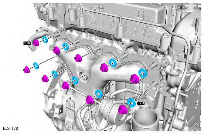
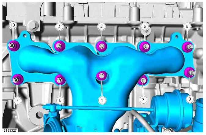
1. CAUTION: Tighten the bolts in the sequence shown. To install, reverse the removal procedure.
Torque: 37 Nm
Turbocharger - Component Location
COMPONENT LOCATION
- Exhaust system mounting flange
- Exhaust manifold
- Engine coolant inlet pipe
- Engine coolant outlet pipe
- Cool atmospheric air inlet from air filter
- Vacuum pipe from inlet manifold
- Engine oil pressure supply
- Turbocharger
- Engine oil return
- Hot compressed air outlet to charge air cooler
Turbocharger - Overview
OVERVIEW
Air charging of the 2.0L GTDi engine is provided by a fixed nozzle Borg Warner K03 turbocharger.
The turbocharger consists of two turbo elements; a turbine and a compressor. These elements are enclosed separately in cast housings and mounted on a common shaft, which rotates in a single semi-floating bearing.
The turbocharger receives water and oil cooling to allow it to maintain the optimum operating temperature and protect the bearings from overheating.
The turbocharger has a pressure operated wastegate which is controlled by the ECM (engine control module).
Turbocharger - System Operation and Component Description
System Operation
OPERATION
The turbocharger is an exhaust-driven centrifugal air compressor which increases power output by supplying compressed air to the engine. The turbine wheel of the turbocharger uses the engine's exhaust gasses to drive the compressor wheel at speeds of up to 195,000 RPM. The compressor wheel draws in fresh air which is compressed and delivered through a charge air cooler to the engine cylinders.
By turbocharging the engine, the pressure and density of the air entering the cylinders is increased, and therefore so is the amount of oxygen. This enables a greater quantity of fuel to be injected, thus increasing the engine's power output, improving fuel consumption and the ability to maintain power at higher altitudes.
The internal components are oil and coolant cooled. Engine oil and coolant are circulated through the center housing which acts as a heat barrier between the "hot" turbine and the "cold" compressor. The bearing is a sleeve type and is lubricated by engine oil. Oil is circulated to the turbocharger center housing and returned to the sump through an oil drain to the cylinder block.
Component Description
DESCRIPTION
Turbocharger
- Exhaust manifold
- Engine coolant outlet pipe to water outlet
- Cool atmospheric air inlet from air filter
- Wastegate pressure actuator
- Pressure hoses
- Wastegate control solenoid valve
- Hot compressed air outlet to charge air cooler
- Engine oil return pipe to cylinder block
- Exhaust system mounting flange
- Wastegate
- Engine coolant inlet pipe from cylinder block
- Engine oil pressure supply pipe from cylinder block
- Vacuum connection to inlet manifold
- Engine coolant inlet pipe connection
- Engine oil pressure supply pipe connection
- Engine coolant outlet pipe connection
The turbocharger is attached to a sheet steel fabricated exhaust manifold with integral sheet steel turbine housing. The exhaust manifold is attached to the cylinder head with studs and nuts and sealed with a layered gasket. The manifold is fabricated in two layers which impedes heat dissipation.
The fabricated steel manifold has lighter weight than a cast manifold and also promotes faster warm-up of the catalytic converter, reducing emissions.
Manifold and Turbocharger Section
The manifold incorporates the turbocharger wastegate which is connected by a rod to the pressure actuator which is mounted on the turbocharger. The turbocharger turbine is also located within the manifold fabrication. The turbocharger housing is attached to the manifold with a two piece clamp which is secured with a bolt and nut.
The turbocharger compressor is located within the turbocharger housing. Pressure pipes are connected to the inlet air side of the turbocharger housing and are connected to a turbocharger wastegate control solenoid valve. When the solenoid is energized by a PWM (pulse width modulation) signal from the ECM (engine control module), the valve opens and pressure is used to operate the wastegate pressure actuator.
The wastegate will start to open at about 0.35 bar (5.07 lbf/in
READ NEXT:
 Accessory Drive - GTDi 2.0L Petrol
Torque Specifications
Accessory Drive Belt
Removal
NOTE: Some illustrations may show the engine removed for clarity.
1. Disconnect the battery ground cable.
Refer to: Specifications (414-01 Battery
Starting System - GTDi 2.0L Petrol
Starting System - Component
Location
COMPONENT LOCATION
Solenoid
12V supply from battery
Solenoid power supply from Battery Junction Box (BJB)
Starter motor
Pinion gear
Starting System - Overv
Engine Ignition - GTDi 2.0L Petrol
Engine Ignition
Principles of Operation
For a detailed description of the ignition system, refer to the relevant
Description and Operation section in the workshop
manual. REFER to: (303-07D)
Inspecti
SEE MORE:
Important information
The information contained in this handbook covers all vehicle derivatives and
optional equipment,
some of which may not be fitted to your vehicle. Due to printing cycles, this
handbook may include
descriptions of options before they become generally available.
The vehicle options, hardware an
Symbols used in this handbook
Safety warnings indicate either a procedure which must be followed
precisely, or
information that should be considered with great care, in order to avoid the
possibility
of personal injury.
Cautions indicate either a procedure which must be followed precisely, or
information that
should
