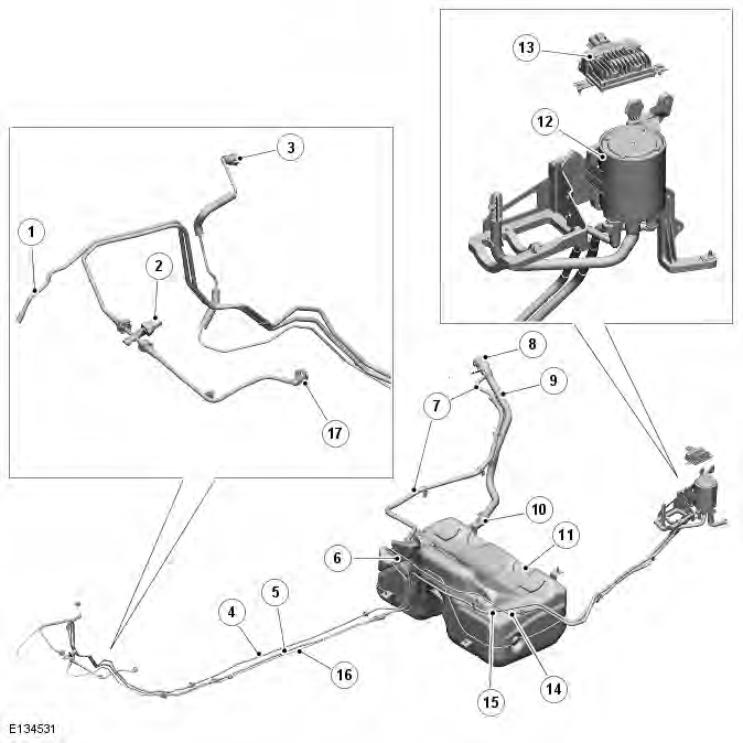
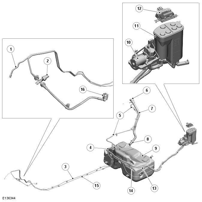
Range Rover Evoque: Fuel Tank and Lines - Component Location
Land Rover Range Rover Evoque L538 (2011–2018) Service Manual / Fuel System / Fuel Tank and Lines - GTDi 2.0L Petrol / Fuel Tank and Lines - Component
Location
Component Location
COMPONENT LOCATION - ROW

- Connection to purge valve
- Fuel Low Pressure (LP) sensor
- Fuel fired booster heater - fuel supply pipe connection (if fitted)
- LP fuel supply pipe
- Fuel fired booster heater - fuel supply pipe (if fitted)
- Fuel pump delivery module
- Fuel tank breather pipe
- Fuel filler cap
- Fuel tank filler pipe
- Fuel tank inlet hose and check valve
- Fuel tank
- Charcoal canister (reference only)
- Fuel Pump Driver Module (FPDM)
- Fuel tank vent breather pipe to charcoal canister
- Fuel vapor pipe from charcoal canister to purge valve
- Fuel vapor pipe to purge valve
- LP fuel supply connection to High Pressure (HP) pump
COMPONENT LOCATION - NAS

- Connection to purge valve
- Fuel Low Pressure (LP) sensor
- LP fuel supply pipe
- Fuel pump delivery module
- Fuel tank breather pipe
- Fuel filler cap
- Fuel tank filler pipe
- Fuel tank inlet hose and check valve
- Fuel tank
- DMTL pump
- Charcoal canister (reference only)
- Fuel Pump Driver Module (FPDM)
- Fuel tank vent breather pipe to charcoal canister
- Fuel vapor pipe from charcoal canister to purge valve
- Fuel vapor pipe to purge valve
- LP fuel supply connection to High Pressure (HP) pump
Overview
OVERVIEW
The fuel system is divided into 2 sub systems:
- Low pressure system
- High pressure system.
The low pressure system features the following components:
- Fuel tank
- Fuel pump delivery module in tank
The low pressure system pressure is 4.5 bar (65.3 lbf/in
READ NEXT:
 Fuel Tank and Lines - System
Operation and Component Description
Control Diagram
NOTE: A = Hardwired
Battery
Battery Junction Box (BJB)
Fuel Pump Driver Module (FPDM)
Fuel pump delivery module
Engine Control Module (ECM)
Central Junction Box (CJB)
System O
 Fuel Filter
Special Tool(s)
310-123
Locking Ring, Fuel Tank
Removal
WARNINGS:
Wait for a minimum of 1 minute after the engine has stopped before
carrying out any repair to the fuel injection
system.
Avoid flame
 Fuel Tank
Special Tool(s)
310-123
Locking Ring, Fuel Tank
Removal
WARNINGS:
Fuel may still be present in the fuel tank after draining.
Avoid flames, sparks or lighted substances.
CAUTIONS:
Extreme cleanliness
SEE MORE:
 Navigation poi voice commands
To request the display of POI (Point Of Interest)
identifiers on the navigation display:
- Say Navigation, followed by the name of
the desired P.O.I category from the
following list;
- Petrol station/Petrol.
- Parking/Car park.
- Land Rover Dealer.
- Hospital.
- Golf course.
- Tourist info
 Electronic Engine Controls
Principles of Operation
For a detailed description of the 2.0L GTDi petrol electronic engine
controls, refer to the relevant Description and Operation
section in the workshop manual. REFER to: (303-14B Electronic Engine Controls -
GTDi 2.0L Petrol)
Inspection and Verification
CAUTION: Diagnosis by
© 2011-2026 Copyright www.rrevoque.org

