Range Rover Evoque: Fuel Tank
Special Tool(s)
 310-123
Locking Ring, Fuel Tank
Removal
WARNINGS: Fuel may still be present in the fuel tank after draining.
Avoid flames, sparks or lighted substances.
CAUTIONS: Extreme cleanliness must be exercised when handling these components.
Make sure that all openings are sealed. Use new blanking caps.
NOTES: Removal steps in this procedure may contain installation details.
Some variation in the illustrations may occur, but the essential information is always correct.
1. WARNING: Make sure to support the vehicle with axle stands. Raise and support the vehicle.
2. Disconnect the battery ground cable.
Refer to: Specifications (414-01 Battery, Mounting and Cables, Specifications).
3. Refer to: Rear Seat Cushion (501-10 Seating, Removal and Installation).
4. Refer to: Fuel Tank Draining (310-00 Fuel System - General Information, General Procedures).
5. Refer to: Driveshaft - GTDi 2.0L Petrol (205-01 Driveshaft, Removal and Installation).
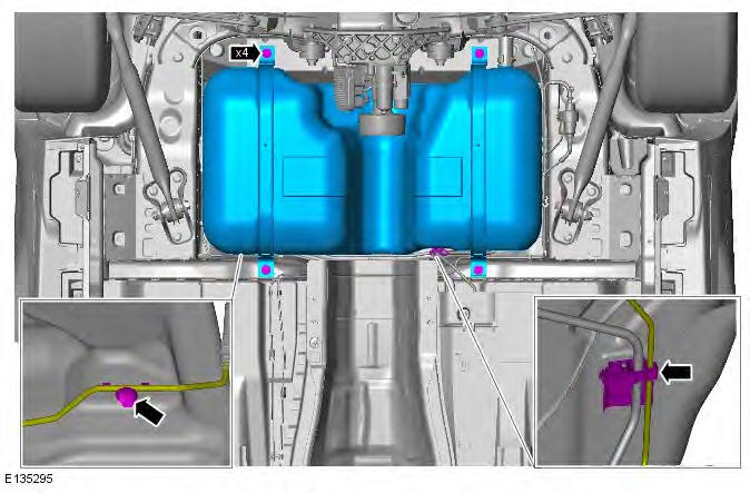
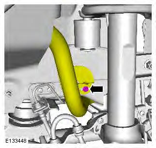
6.
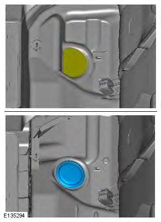
7.
8.
9. Torque: 5 Nm
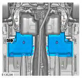
10. Torque: 24 Nm
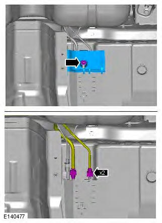
11. CAUTION: Be prepared to collect escaping fuel.
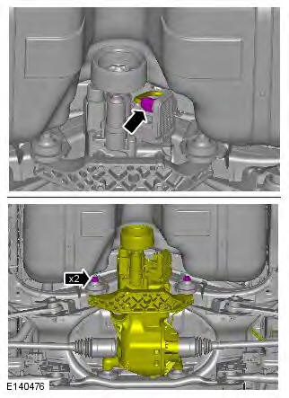
12. NOTE: Using a suitable transmission jack support the differential case.
Torque: 110 Nm
13. CAUTION: Using a suitable transmission jack lower the fuel tank.
Torque: 25 Nm
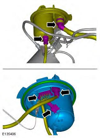
14. CAUTION: Be prepared to collect escaping fuel.
NOTE: Do not disassemble further if the component is removed for access only.
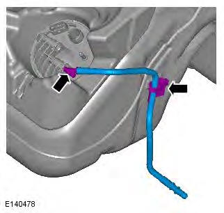
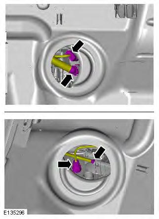
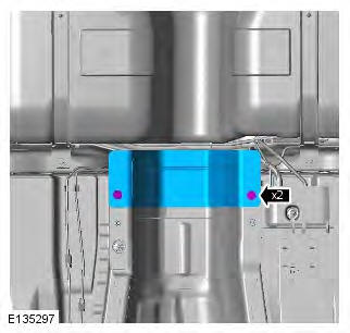
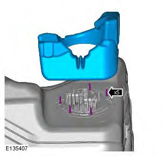
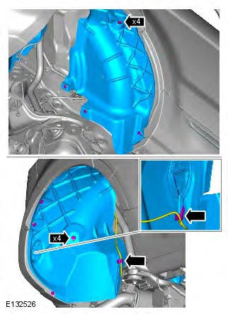
15.
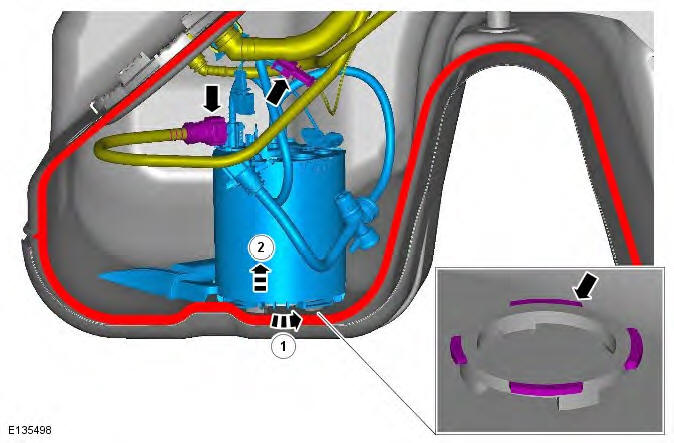
16. CAUTIONS: Extreme cleanliness must be exercised when handling these components.
Make sure that the seal is correctly positioned.
Failure to follow this instruction may result in damage to the vehicle.
NOTE: Some variation in the illustrations may occur, but the essential information is always correct.
- Special Tool(s): 310-123
- Torque: 200 Nm
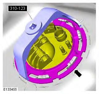
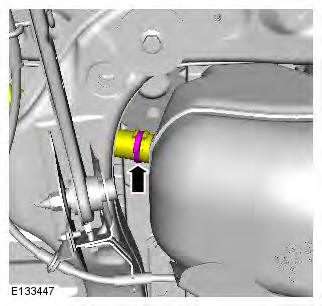
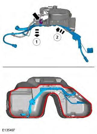
17.
18.
19.
Installation
1. To install, reverse the removal procedure.
Fuel Tank Filler Pipe
Removal
WARNING: Avoid flames, sparks or lighted substances.
CAUTIONS: Extreme cleanliness must be exercised when handling these components.
Make sure that all openings are sealed. Use new blanking caps.
NOTES: Removal steps in this procedure may contain installation details.
Some variation in the illustrations may occur, but the essential information is always correct.
1. WARNING: Make sure to support the vehicle with axle stands. Raise and support the vehicle.
2. Disconnect the battery ground cable.
Refer to: Specifications (414-01 Battery, Mounting and Cables, Specifications).
3. Remove the rear wheel.
Refer to: Wheel and Tire (204-04 Wheels and Tires, Removal and Installation).
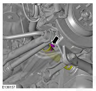
4.
5. Torque: 10 Nm
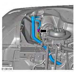
6.
7. WARNING: This procedure involves fuel handling.
Be prepared for fuel spillage at all times and always observe fuel handling precautions. Failure to follow these instructions may result in personal injury.
8.
Installation
1. To install, reverse the removal procedure.
READ NEXT:
 Fuel Tank and Lines - Diagnosis and Testing
Principles of Operation
For a detailed description of the fuel tank and lines systems, refer to the
relevant Description and Operation section in the
workshop manual. REFER to: (310-01B Fuel Tank and
Speed Control
Speed Control Actuator
Removal
1. Refer to: Accelerator Pedal (310-02 Acceleration Control, Removal
and Installation).
Installation
1. To install, reverse the removal procedure.
Speed Control Deactiv
SEE MORE:
Important information
The information contained in this handbook covers all vehicle derivatives and
optional equipment,
some of which may not be fitted to your vehicle. Due to printing cycles, this
handbook may include
descriptions of options before they become generally available.
The vehicle options, hardware an
Symbols used in this handbook
Safety warnings indicate either a procedure which must be followed
precisely, or
information that should be considered with great care, in order to avoid the
possibility
of personal injury.
Cautions indicate either a procedure which must be followed precisely, or
information that
should
