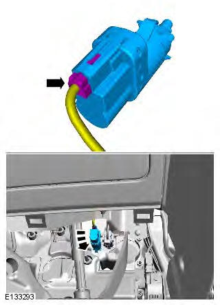
Range Rover Evoque: Speed Control

Range Rover Evoque. Speed Control

Speed Control Actuator

Removal

1. Refer to: Accelerator Pedal (310-02 Acceleration Control, Removal and Installation).

Installation

1. To install, reverse the removal procedure.

Speed Control Deactivator Switch

Removal

NOTE: Removal steps in this procedure may contain installation details.

1. CAUTION: LH illustration shown, RH is similar.
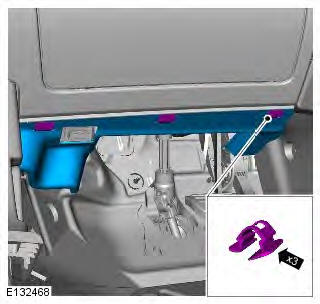
Range Rover Evoque. Speed Control

2.

Range Rover Evoque. Speed Control

Installation

1. To install, reverse the removal procedure.

Speed Control Switch

Removal

NOTE: Removal steps in this procedure may contain installation details.

1. Make the air bag supplemental restraint system (SRS) safe.

Refer to: Standard Workshop Practices (100-00 General Information, Description and Operation).

2. Disconnect the battery ground cable.

Refer to: Specifications (414-01 Battery, Mounting and Cables, Specifications).

3. Refer to: Driver Air Bag Module (501-20B Supplemental Restraint System, Removal and Installation).

4. Torque: 1.3 Nm
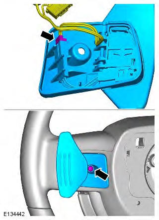
Range Rover Evoque. Speed Control

5. CAUTION: Take extra care not to damage the edges of the component.

Torque: 2.1 Nm
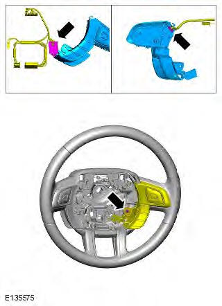
Range Rover Evoque. Speed Control

6. NOTE: Do not disassemble further if the component is removed for access only.
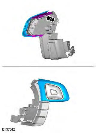
Range Rover Evoque. Speed Control

Installation

1. To install, reverse the removal procedure.

READ NEXT:

 Climate Control System

 Climate Control System - General Information

Climate Control Lubricants, Fluids, Sealers and Adhesives General Specification Capacities Refrigerant oil adding capacities for replacment parts NOTE: Rotate the A/C compressor shaft at least 6 t

 Climate Control

SEE MORE:

 Checking the tyre pressure after a repair

When driving the vehicle, if you experience vibrations, abnormal steering, or noises, reduce speed immediately. Drive with extreme caution and reduced speed to the first safe place to stop the vehicle. Visually examine the tyre, and check its pressure. If there are any signs of damage or

 Transmission Control Module (TCM), Gear Shift Module (GSM)

TRANSMISSION CONTROL MODULE (TCM) TCM Neutral 'N' position Park 'P' position Position sensor/manual shaft Electrical connector The TCM is located on the top of the transmission casing and is connected on the high speed CAN (controller area network) bus to send and receive information to and

© 2011-2024 Copyright www.rrevoque.org