Range Rover Evoque: Hydraulic Brake Actuation
Hydraulic Brake Actuation LHD AWD/RHD AWD - Component Location
NOTE: RHD (right-hand drive) installation shown, LHD (left-hand drive) installation similar.
COMPONENT LOCATION
- Brake pedal
- Hydraulic pipes
- Integrated HCU (hydraulic control unit) and ABS (anti-lock brake system) module
- Brake master cylinder and fluid reservoir
Hydraulic Brake Actuation LHD AWD/RHD AWD - Overview
OVERVIEW
The hydraulic brake system is a diagonally split, dual circuit system and consists of the brake pedal, brake master cylinder, fluid reservoir, HCU (hydraulic control unit), and the brake pipes and hoses.
The preformed rigid brake pipes distribute pressure from the master cylinder to flexible hoses connected to the front and rear calipers, via the integrated HCU and ABS (anti-lock brake system) module.
Hydraulic Brake Actuation LHD AWD/RHD AWD - System Operation and Component Description
System Operation
PRINCIPLES OF OPERATION
As the brake pedal is pressed, the front push rod in the brake booster pushes the master cylinder primary piston along the bore of the housing. This produces pressure in the primary pressure chamber and in conjunction with the primary spring, overcomes the secondary spring and simultaneously moves the secondary piston along the bore.
The initial movement of the pistons away from the piston stops closes the primary and secondary center valves located inside the master cylinder. Further movement of the pistons then pressurizes the fluid in the primary and secondary chambers and the brake circuits. The fluid in the chambers behind the pistons is unaffected by the movement of the pistons and will flow unrestricted through the inlet ports, between the chambers and the reservoir.
Pressurized fluid enters the HCU (hydraulic control unit). The HCU then modulates the supply of pressurized fluid to the brakes under control of the ABS (anti-lock brake system) module.
Refer to: Anti-Lock Control - Traction Control - AWD (206-09B Anti-Lock Control - Traction Control, Description and Operation).
Component Description
BRAKE PEDAL
- LHD (left-hand drive) brake pedal (automatic transmission)
- RHD (right-hand drive) brake pedal (manual transmission)
- Switch operating plate
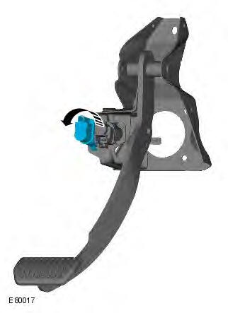
- Stoplamp switch
- Brake diagnostic switch
The brake pedal is mounted in a bracket attached to the rear side of the engine bulkhead. The brake pedal is connected to the brake booster push rod with a clevis pin.
The stoplamp switch and the brake diagnostic switch are mounted on the brake pedal bracket and operated by a plate attached to the brake pedal. Both switches are single pole switches hardwired to the CJB (central junction box), to give independent signals of brake pedal operation.
BRAKE MASTER CYLINDER AND FLUID RESERVOIR
- Brake fluid reservoir cap
- Brake fluid level switch
- Brake fluid reservoir
- Secondary circuit inlet port
- Primary circuit inlet port
- Brake master cylinder
- Screw
- Secondary circuit outlet port
- Primary circuit outlet port
- Clutch circuit outlet port (manual transmission only)
The brake master cylinder is attached to the front of the brake booster, on the driver's side of the engine compartment.
The brake master cylinder is a tandem design that supplies pressure to two independent (primary and secondary) hydraulic circuits. Each circuit is connected between the calipers of diagonally opposing front and rear wheels to provide a fail safe brake system.
A reservoir is mounted on top of the master cylinder and retains sufficient volume of hydraulic fluid to allow for normal system use, and to compensate for the replenishment of the system as the brake linings wear. The reservoir is internally divided to provide an independent supply of fluid to each brake circuit, and prevents a single fluid leak from disabling both primary and secondary brake circuits. If a failure occurs in one brake hydraulic circuit the remaining circuit will still operate effectively, although brake pedal travel and vehicle braking distances will increase.
On vehicles with manual transmission, the brake fluid reservoir also supplies hydraulic fluid for operation of the clutch assembly.
Brake Fluid Level Switch
- Contact carrier
- Contact
- Float
The reservoir incorporates a brake fluid level switch that is hardwired to the CJB. When the reservoir fluid falls to a predetermined low level, the switch contacts close and provide a signal feed back to the CJB. The CJB then sends a message on the high speed CAN (controller area network) bus to the instrument cluster, which illuminates the brake fluid warning indicator lamp.
Refer to: Instrument Cluster (413-01 Instrument Cluster, Description and Operation).
HYDRAULIC CONTROL UNIT
- LH (left-hand) front caliper port
- ABS module
- RH (right-hand) front caliper port
- Primary circuit port
- LH rear caliper port
- HCU
- RH rear caliper port
- Secondary circuit port
The HCU is located on the rear LH side of the engine compartment and is an integral component with the ABS module. The HCU is a four channel unit that modulates the supply of hydraulic pressure to the brakes under the control of the ABS module.
The primary and secondary outlet ports of the master cylinder are connected via 8 mm (0.315 in) diameter brake pipes to the primary and secondary circuits of the HCU. The primary circuit in the HCU provides two separate outlet ports to the RH front and LH rear brakes. The secondary circuit in the HCU provides two separate outlet ports to the LH front and RH rear brakes.
The HCU incorporates three brake operating modes as follows:
- Normal braking / EBD (electronic brake force distribution).
- ABS braking.
- Active braking.
As the HCU and ABS module is a fully integrated unit, details of the HCU and ABS functionality, including the three braking modes, are contained in the Anti-Lock Control - Traction Control section of the manual.
Refer to: Anti-Lock Control - Traction Control - AWD (206-09B Anti-Lock Control - Traction Control, Description and Operation).
Servicing Information
The ABS module and HCU form a single component and must not be separated. The ABS module and HCU assembly is supplied in a pre-filled state. After installation, the hydraulic brake system only requires a conventional bleed of the system; there is no requirement to pressure bleed the system.
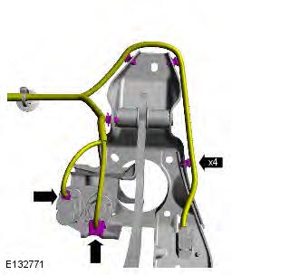
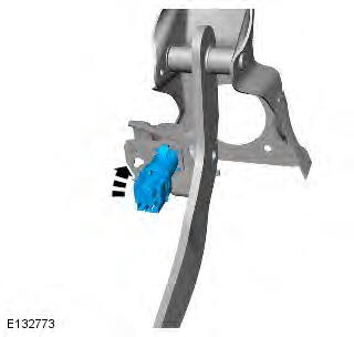
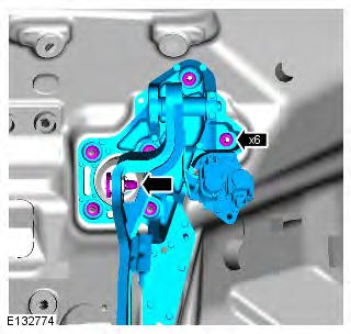
Brake Pedal and Bracket
Removal
NOTE: Removal steps in this procedure may contain installation details.
All vehicles
1. Make the SRS system safe.
Refer to: Standard Workshop Practices (100-00 General Information, Description and Operation).
2. Refer to: Driver Lower Air Bag Module (501-20B Supplemental Restraint System, Removal and Installation).
3. Refer to: Accelerator Pedal (310-02 Acceleration Control, Removal and Installation).
4.
Left-hand drive vehicles
5. Torque: 25 Nm
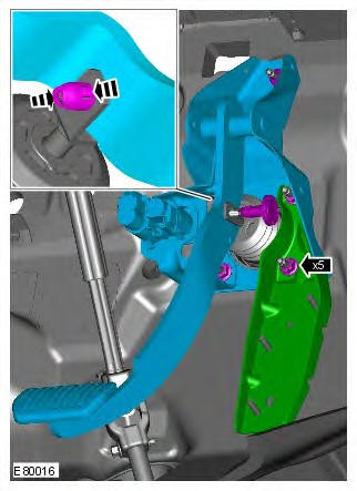
6. NOTE: Do not disassemble further if the component is removed for access only.
7.
Right-hand drive vehicles
8. Torque: 25 Nm
9.
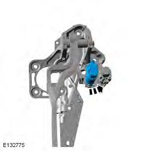
10.

Installation
1. To install, reverse the removal procedure.
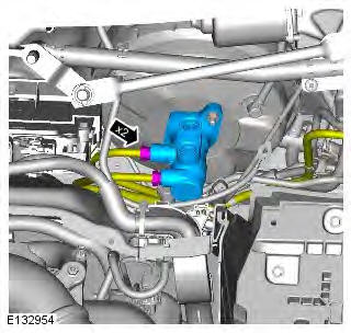
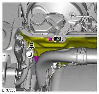
Brake Master Cylinder
Removal
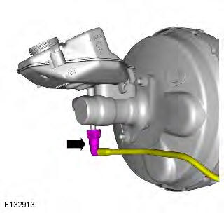
CAUTION: If brake fluid is spilt on the paintwork, the affected area must be immediately washed down with cold water.
NOTE: Removal steps in this procedure may contain installation details.
All vehicles
1. WARNING: Make sure to support the vehicle with axle stands. Raise and support the vehicle.
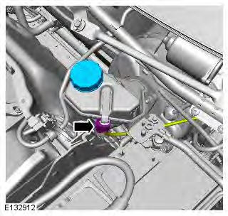
2. Refer to: Brake Fluid Reservoir (206-06 Hydraulic Brake Actuation, Removal and Installation).
3. WARNING: Fluid loss is unavoidable, use absorbent cloth or a container to collect the fluid.
CAUTION: Make sure that all openings are sealed.
Use new blanking caps.
Torque: 17 Nm
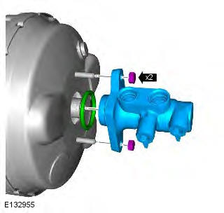
Right-hand drive vehicles
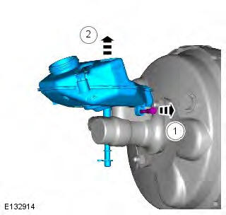
4.
5. Torque: 10 Nm
All vehicles
6. CAUTION: Discard the seal. Torque: 25 Nm
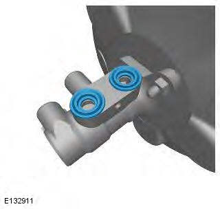
Installation
1. CAUTION: A new O-ring seal is to be installed. To install, reverse the removal procedure.
2. Refer to: Brake System Bleeding (206-00 Brake System - General Information, General Procedures).
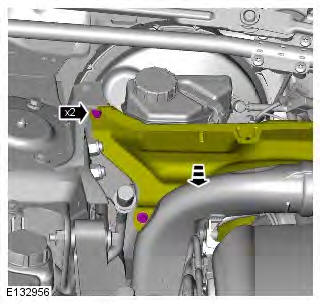
Brake Fluid Reservoir
Removal
CAUTION: If brake fluid is spilt on the paintwork, the affected area must be immediately washed down with cold water.
NOTE: Removal steps in this procedure may contain installation details.
All vehicles
1. Refer to: Plenum Chamber (412-01 Climate Control, Removal and Installation).
2.
Left-hand drive vehicles
3. Refer to: Battery (414-01 Battery, Mounting and Cables, Removal and Installation).
Vehicles with manual transmission
4. WARNING: Fluid loss is unavoidable, use absorbent cloth or a container to collect the fluid.
All vehicles
5. WARNING: Fluid loss is unavoidable, use absorbent cloth or a container to collect the fluid.
6. CAUTION: Discard the seals.
NOTE: Make sure that all openings are sealed. Use new blanking caps.
Installation
All vehicles
1. CAUTION: Install the new seals. To install, reverse the removal procedure.
2. Refer to: Brake System Bleeding (206-00 Brake System - General Information, General Procedures).
Vehicles with manual transmission
3. Refer to: Clutch System Bleeding (308-00 Manual Transmission/Transaxle and Clutch - General Information, General Procedures).
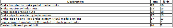
Hydraulic Brake Actuation
Torque Specifications
READ NEXT:
 Power Brake Actuation
Brake Booster - Component Location
COMPONENT LOCATION - 2.2L Td4
NOTE: RHD (right-hand drive) installation shown, LHD (left-hand drive)
installation similar
Brake booster
Vacuum pipe (vehicles wi
Anti-Lock Control
Torque Specifications
Anti-Lock Brake System (ABS) Module
Removal
CAUTIONS:
If brake fluid is spilt on the paintwork, the affected area must be
immediately washed down with cold water.
Make sure th
SEE MORE:
Important information
The information contained in this handbook covers all vehicle derivatives and
optional equipment,
some of which may not be fitted to your vehicle. Due to printing cycles, this
handbook may include
descriptions of options before they become generally available.
The vehicle options, hardware an
Symbols used in this handbook
Safety warnings indicate either a procedure which must be followed
precisely, or
information that should be considered with great care, in order to avoid the
possibility
of personal injury.
Cautions indicate either a procedure which must be followed precisely, or
information that
should
