Range Rover Evoque: Navigation System
Navigation System
Principles of Operation
NOTE: This navigation system is installed in selected Asia market vehicles only.
For a detailed description of the navigation system, refer to the relevant Description and Operation section of the workshop manual. REFER to: (415-01 Information and Entertainment System)
Inspection and Verification
CAUTION: Diagnosis by substitution from a donor vehicle is NOT acceptable. Substitution of control modules does not guarantee confirmation of a fault, and may also cause additional faults in the vehicle being tested and/or the donor vehicle.
NOTE: Check and rectify basic faults before beginning diagnostic routines involving pinpoint tests.
1. Verify the customer concern
2. Visually inspect for obvious signs of damage, water ingress and system integrity
Visual Inspection
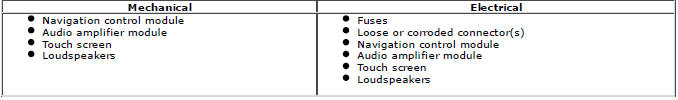
3. If an obvious cause for an observed or reported concern is found, correct the cause (if possible) before proceeding to the next step
4. If the cause is not visually evident, verify the symptom and refer to the Symptom Chart
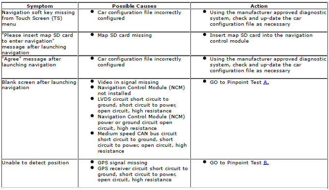
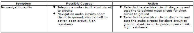
Symptom Chart
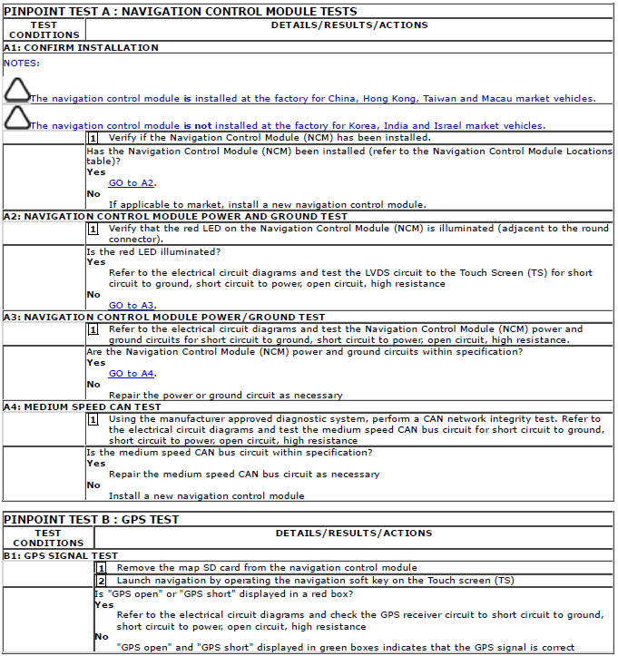
Pinpoint Tests
NOTE: If the control module or a component is suspect and the vehicle remains under manufacturer warranty, refer to the Warranty Policy and Procedures manual (section B1.2), or determine if any prior approval Program is in operation, prior to the installation of a new module/component.
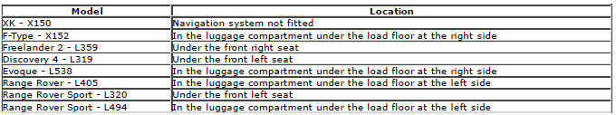
Navigation Control Module Locations

DTC Index
For a list of diagnostic trouble codes that could be logged on this vehicle, please refer to Section 100-00.
REFER to: Diagnostic Trouble Code (DTC) Index - DTC: Navigation Control Module (NCM) (100-00, Description and Operation) / Diagnostic Trouble Code (DTC) Index - DTC: Touch Screen (TS) (100-00 General Information, Description and Operation).
READ NEXT:
 Multifunction Electronic Modules
Torque Specifications
Front Door Module (FDM)
Removal
NOTE: Removal steps in this procedure may contain installation details.
1. Disconnect the battery ground cable.
Refer to: Specifications (414-01
SEE MORE:
Important information
The information contained in this handbook covers all vehicle derivatives and
optional equipment,
some of which may not be fitted to your vehicle. Due to printing cycles, this
handbook may include
descriptions of options before they become generally available.
The vehicle options, hardware an
Symbols used in this handbook
Safety warnings indicate either a procedure which must be followed
precisely, or
information that should be considered with great care, in order to avoid the
possibility
of personal injury.
Cautions indicate either a procedure which must be followed precisely, or
information that
should
