Range Rover Evoque: Power Steering FWD
Component Location
- Steering gear
- Rubber seal assembly
- Heat shield
Overview
The vehicle is fitted with EPS (electric power steering), provided by a ZF Servolectric steering gear unit with variable ratio, rack and pinion steering and speed sensitive power assistance. Power assistance is from an electric motor attached to the steering gear.
The steering gear also incorporates:
- A power steering control module, on the end of the electric motor.
- A reduction gear.
- A torque sensor on the gear mechanism.
Power assistance is controlled by the power steering control module, which uses the electric motor to apply an axial force on the steering rack via the reduction gear. The level of power assistance depends on the steering torque applied with the steering wheel, vehicle speed and terrain response mode selected. The power steering control module also uses the electric motor to provide the following assistance features:
- Pull drift compensation.
- Assistance changes during Eco Stop/Start functions.
- Assistance reduction if system overheats.
- Assistance reduction if low or high voltage.
- Assistance reduction for system stability optimisation.
- Soft end stops.
- Park assist support (where fitted).
- Refer to: Parking Aid (413-13 Parking Aid, Description and Operation).
System Operation and Component Description
Control Diagram
NOTE: A = Hardwired; D = High speed CAN (controller area network) bus.
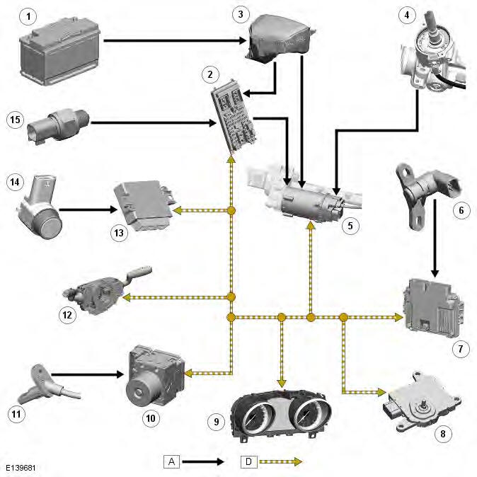
- Battery
- CJB (central junction box)
- EJB (engine junction box)
- Torque sensor
- Power steering control module
- CKP (crankshaft position) sensor
- ECM (engine control module)
- TCM (transmission control module) (automatic transmission only)
- Instrument cluster
- ABS (anti-lock brake system) module
- Wheel speed sensor (4 off)
- Steering angle sensor (integrated into clockspring)
- Parking aid module (if park assist system fitted)
- Parking aid slot sensor (2 off)
- Reverse gear sensor (manual transmission only)
System Operation
For the EPS (electric power steering) system to provide assistance the engine must be running.
If a fault occurs which affects control of the electric motor, the power steering control module disables the electric motor.
The driver no longer benefits from power assisted steering, but incorrect control of the electric motor is prevented and the vehicle remains fully steerable, although with greater physical effort.
VARIABLE POWER ASSISTANCE
At low speeds, when tire resistance to steering inputs is highest, more assistance is applied to reduce the steering wheel torque to comfortable levels. At higher speeds, when tire resistance to steering inputs is less, less assistance is required.
PULL DRIFT COMPENSATION
This feature aids the driver by compensating for the accumulated effects of various factors that contribute to the pull/ drift of the vehicle. The feature reduces the steering wheel torque offset that the driver feels while driving in a straight line, by applying a counter torque. The vehicle will drift less if the driver's hands are taken off the steering wheel, and steering effort in general is reduced.
ASSISTANCE REDUCTION IF SYSTEM OVERHEATS OR VOLTAGE IS TOO HIGH OR LOW
This feature ensures that the driver's steering requirements continue to be supported during various extreme conditions including:
- Extreme voltage fluctuations (over and under voltage).
- Extreme high temperature.
- Steering system vibration optimization, detected for example when steering on a low friction surface.
A temperature sensor is installed in the power steering control module for overload protection of the electric motor. The power steering control module reduces the level of power assistance if the temperature of the electric motor is too high, to reduce the amount of heat generated.
Temperature overload can occur at high ambient temperatures combined with high levels of steering activity, especially when stationary. A temperature overload can also occur if an attempt is made to repeatedly turn the front wheels against a solid object such as a kerb, which the power steering control module detects by comparing the control signals to the electric motor with the motion of the motor. Reducing power assistance in this situation protects the power steering components against excessive mechanical stresses and signals to the driver that there is a solid object preventing the wheels turning.
The reduction of power assistance begins at a temperature of approximately 110
READ NEXT:
 Steering Linkage
Tie Rod End
Special Tool(s)
205-754A
Splitter, Ball Joints
Removal
NOTE: RH illustration shown, LH is similar.
1. WARNING: Make sure to support the vehicle with axle stands.
Raise and support the vehi
Steering Column
Steering Column - Component Location
Upper column
Steering wheel
Intermediate shaft
Steering Column - Overview
The steering column consists of an intermediate shaft, the upper column and
the st
Steering Column Switches
Torque Specifications
Steering Column Multifunction Switch
Removal
NOTES:
Removal steps in this procedure may contain installation details.
Removal of the windshield wiper switch assembly is identic
SEE MORE:
Important information
The information contained in this handbook covers all vehicle derivatives and
optional equipment,
some of which may not be fitted to your vehicle. Due to printing cycles, this
handbook may include
descriptions of options before they become generally available.
The vehicle options, hardware an
Symbols used in this handbook
Safety warnings indicate either a procedure which must be followed
precisely, or
information that should be considered with great care, in order to avoid the
possibility
of personal injury.
Cautions indicate either a procedure which must be followed precisely, or
information that
should
