Range Rover Evoque: Rear Suspension AWD
Component Location
- RH (right-hand) spring and damper assembly
- Stabilizer link
- Stabilizer bar
- LH (left-hand) spring and damper assembly
- Wheel knuckle
- Hub
- Longitudinal link
- Rear transverse link
- Front transverse link
- Subframe
Overview
The rear suspension features long travel McPherson struts to optimize on and off road performance.
The suspension components are mounted on a subframe which provides a rigid platform attached to the underside of the vehicle body. The subframe is mounted to the body on four bushes which have differing compression rates to absorb lateral and longitudinal loading from cornering and braking.
System Operation and Component Description
System Operation
Not applicable.
Component Description
SPRING AND DAMPER
NOTE: Adaptive dynamics damper shown, standard damper similar.
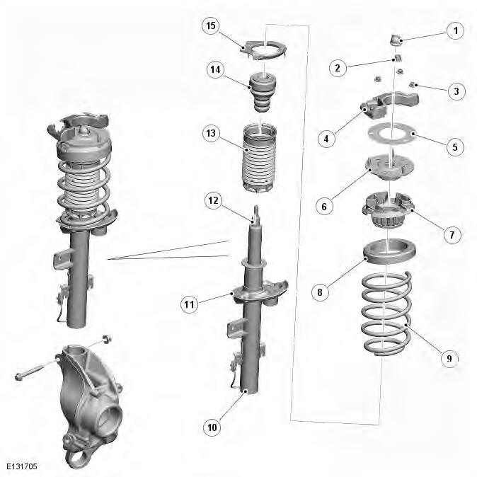
- Boot (swish cap)
- Locknut
- Nuts - top mount (3 off)
- Vibration damper
- Paper gasket
- Top mount
- Upper spring seat
- Spring isolator
- Spring
- Damper body
- Spring seat
- Damper piston rod
- Boot
- Spring aid
- Spring isolator
The spring and damper assembly consists of a damper with a coil spring located on a welded spring seat on the damper tube. The lower end of the damper body locates in the wheel knuckle and is clamped with a nut and bolt.
Depending on vehicle specification, the damper is either a conventional damper or a MagneRide damper. The conventional damper functions by restricting the flow of hydraulic fluid through a piston in the damper. The MagneRide damper also functions by restricting the flow of a fluid through the piston, but instead of hydraulic fluid it contains a fluid whose flow properties change when subjected to a magnetic field, which enables the damping rate to be varied.
Refer to: Vehicle Dynamic Suspension (204-05 Vehicle Dynamic Suspension, Description and Operation).
The damper rod is located through a central hole in the top mount assembly. The rod is threaded at its outer end. A self-locking nut secures the damper rod to the top mount. A spring aid is fitted to the upper spring seat to prevent the damper contacting the top mount during full suspension compression, and also to assist the suspension tune. There are different spring aids for conventional and MagneRide dampers. The damper rod is sealed at its exit point from the damper body to retain the fluid within the unit and to prevent the ingress of dirt and moisture. The seal also incorporates a wiper to keep the rod clean. A boot is fitted between the damper body and the upper spring seat and protects the damper piston rod from damage.
The coil spring fitted differs with vehicle specification. Each spring is color coded to identify its rating and fitment requirements.
The lower end of the coil spring is located in a spring seat which is an integral part of the damper body and contains a spring isolator. The spring has a linear rate compression and is inclined to counter cornering forces. The opposite end of the coil spring is also located in a spring isolator which is fitted in the upper spring seat under the top mount assembly.
There are two specifications of the upper spring isolator, which correspond to the spring length, and help to control vehicle trim height. Both spring isolators are made from rubber and reduce noise, produced during damper and spring compression/extension, from being transmitted to the vehicle body. A mass damper is attached to the damper spring seat to absorb vibration and reduce noise intrusion into the vehicle body.
The top mount is fitted with a gasket to prevent the ingress of moisture between the top mount and the turret mounting.
Three nuts attach the studs on the top mount to the suspension turret. Two of the nuts also attach a mass damper to the top of the suspension turret.
Two brackets are welded to the damper body. One bracket provides for the attachment of the stabilizer link. The second bracket provides for the attachment of the brake hose, the wheel speed sensor cable, the electric park brake cable and, on vehicles with dynamic suspension, the MagneRide damper cable. This bracket also positively locates the damper into the wheel knuckle and its location is critical to controlling the vehicle trim height.
TRANSVERSE LINKS
- Bolt
- Bush - inner
- Locknut
- Eccentric bolt
- Bush - inner
- Eccentric cam washer
- Locknut
- Rear transverse link
- Bolt
- Washer
- Bush - outer
- Locknut
- Locknut
- Bush - outer
- Washer
- Bolt
- Front transverse link
Lateral wheel location is provided by two transverse links which are located between the subframe and the wheel knuckle.
The links are long to give excellent camber control. Each link is fitted with dynamic bushes to control the rear camber in a progressive manner as cornering loads increase which gives a limited amount of passive rear wheel steering. The two transverse links are different in their design. The front link is a steel pressing. The rear link is fabricated from squeezed and cropped tube. The links are designed to withstand vehicle jacking loads.
The front transverse link is fitted with bushes which compress under cornering forces to provide a controlled amount of rear wheel toe-in, in addition to the camber control. The front link has a deform point in a central position along its length.
This allows the link to be deformed in the event of a severe lateral rear wheel impact, for example striking a kerb. In the event of a severe lateral impact, the link will permanently deform, absorbing the impact and protecting the subframe from damage. The amount of deformation creates excessive toe-in which is immediately noticeable to the driver.
The rear transverse link is mounted to the subframe using an eccentric bolt and washer which allows for adjustment of the wheel toe angle.
Both transverse links are attached to the subframe with bolts and locknuts. The outer ends of each link locate in mounting holes integral with the wheel knuckle and are secured with bolts and locknuts.
LONGITUDINAL LINK

- Body mounting bracket
- Longitudinal link
- Bolt
- Locknut
- Locknut
- Bolts
- Bush
- Bolt
The longitudinal links are fabricated from squeezed and cropped tube and are located between the wheel knuckle and the vehicle body. The links control the rear suspension in reaction to braking and traction forces.
The rear mounting is forked and locates on either side of a bush pressed into the wheel knuckle. The link is secured with a bolt and locknut which passes through the bush.
The front mounting of the link locates in a bracket which is bolted to the underside of the vehicle sill. The link is fitted with a bush which locates in the bracket and is secured with a bolt and locknut.
WHEEL KNUCKLE AND HUB
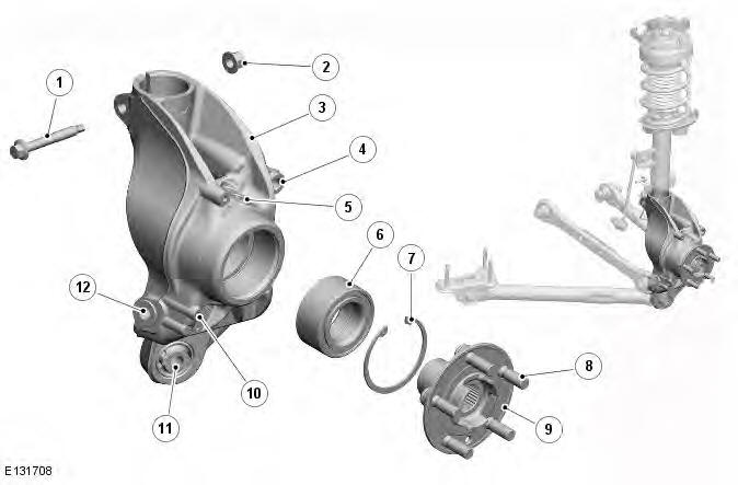
- Clamp bolt
- Locknut
- Wheel knuckle
- Brake caliper attachment
- ABS (anti-lock brake system) wheel speed sensor attachment
- Bearing
- Circlip
- Studs
- Hub
- Disc shield attachment
- Bush - longitudinal link
- Front transverse link attachment
The cast steel wheel knuckle provides the attachment for the transverse links, longitudinal link, spring and damper assembly and the wheel hub and bearing assembly.
An extended lower boss on the knuckle is fitted with a pressed bush and provides for the attachment of the longitudinal link. The link is secured to the knuckle with a bolt and locknut which passes through both the link and the bush.
Two further bosses on the inside face of the wheel knuckle allow for the attachment of the front and rear transverse links which are each secured with a bolt and locknut.
The upper section of the wheel knuckle has a location hole for the damper body. The damper body slides into the hole and locates against an abutment on the damper body. The rear face of the hole is split and allows the damper body to be clamped in the wheel knuckle with a nut and bolt.
Mounting locations are provided for the brake caliper and the brake disc shield. A hole in the top face of the wheel knuckle provides the location for the ABS wheel speed sensor which is secured with a bolt.
The wheel hub is located in the wheel bearing, which is installed in the wheel knuckle and secured with a circlip. The inner face of the wheel bearing incorporates a pulse ring for the ABS sensor.
STABILIZER BAR
- Locknut
- Ball joint
- Link
- Ball joint
- Stabilizer bar
- Bush (2 off)
- Bracket (2 off)
- Bolt (4 off)
- Collar
The stabilizer bar is attached to the rear of the subframe with bushes and mounting brackets. The pressed steel brackets locate over the bushes and are attached to the cross member with bolts screwed into threaded locations in the subframe.
The stabilizer bar has 'anti-shuffle' collars crimped in position on the inside edges of the bushes. The collars prevent sideways movement of the stabilizer bar.
There are different stabilizer bar diameter sizes depending on vehicle specification. Each end of the stabilizer bar curves forwards to attach to a ball joint on a stabilizer link. Each stabilizer link is secured to a bracket on the damper body with a locknut. The links, which are not handed, allow the stabilizer bar to move with the wheel travel.
The stabilizer bar bushes are the compression type which grip the bar under compression by the mounting brackets. When fitting replacement bushes to the bar it is important to ensure the bushes have the correct color code and are correctly orientated to the bar. Failure to correctly align the bushes will result in excessive pre-load (wind-up) in the bushes when the suspension is at its nominal ride height.
Rear Suspension
Coil Spring Suspension

Road Spring and Isolator Identification
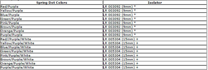
NOTES:
* Indicates a long coil spring and a thin isolator.
+ Indicates a short coil spring and a thick isolator.
To maintain the correct vehicle ride height, make sure that the correct coil spring and isolator are fitted.
The coil spring and isolator should be fitted as a pair.
Always carry out the vehicle ride height check and adjust procedure after fitting a new coil spring and isolator.
Torque Specifications
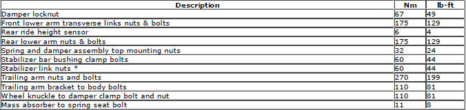
* New nuts/bolts must be installed
READ NEXT:
 Rear Wheel Bearing
Special Tool(s)
204-250
Wheel bearing install and removal tool
204-305
Remover, Wheel Bearing
204-726
Remover/Installer, Wheel Bearing
JLR-204-806
Support Tool, Wheel Knuckle
JLR-204-809
Installer, Re
Front Lower Arm
Removal
NOTES:
Some variation in the illustrations may occur, but the essential
information is always correct.
Front wheel drive transmission illustrations shown, all wheel wheel drive
transmission
Rear Lower Arm AWD
Special Tool(s)
205-857
Remover, Halfshaft
Removal
CAUTION: LH illustration shown, RH is similar.
NOTE: Some variation in the illustrations may occur, but the essential
information is always correct.
SEE MORE:
Important information
The information contained in this handbook covers all vehicle derivatives and
optional equipment,
some of which may not be fitted to your vehicle. Due to printing cycles, this
handbook may include
descriptions of options before they become generally available.
The vehicle options, hardware an
Symbols used in this handbook
Safety warnings indicate either a procedure which must be followed
precisely, or
information that should be considered with great care, in order to avoid the
possibility
of personal injury.
Cautions indicate either a procedure which must be followed precisely, or
information that
should
