Range Rover Evoque: Rear Wheel Bearing
Special Tool(s)
 204-250
Wheel bearing install and removal tool
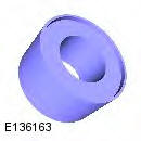
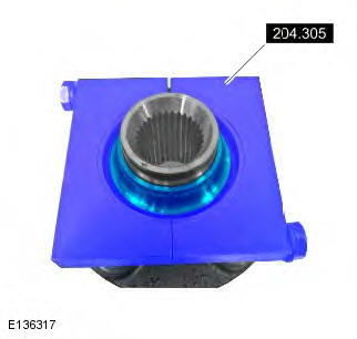
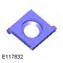 204-305
Remover, Wheel Bearing
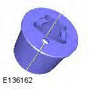
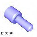
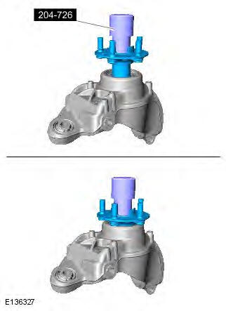
 204-726
Remover/Installer, Wheel Bearing
 JLR-204-806
Support Tool, Wheel Knuckle
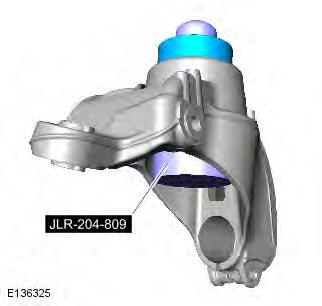
 JLR-204-809
Installer, Rear Wheel Bearing
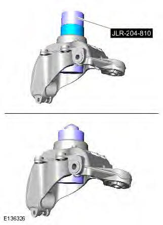
 JLR-204-810
Installer, Rear Wheel Bearing
General Equipment
- Copper Hammer
- Hydraulic press
- Punch
- Vise
Removal
1. WARNING: Make sure to support the vehicle with axle stands. Raise and support the vehicle.
2. Refer to: Wheel Knuckle (204-02 Rear Suspension, Removal and Installation).
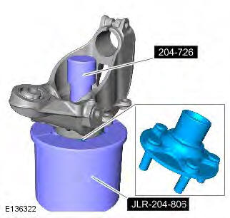
3.
- Special Tool(s): JLR-204-806
- Special Tool(s): 204-726
- General Equipment: Hydraulic press
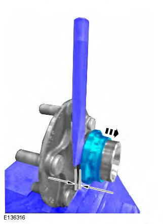
4.
- General Equipment: Vise
- General Equipment: Copper Hammer
- General Equipment: Punch
5.
- Special Tool(s): 204-305
- General Equipment: Hydraulic press
6. Clean all the mating faces and reusable parts thoroughly and check for damage.
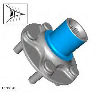
7.
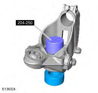
8. NOTE: Note the orientation of the component prior to removal.
- Special Tool(s): 204-250
- General Equipment: Hydraulic press
Installation
1. CAUTION: Make sure that the area around the component is clean and free of foreign material.
Special Tool(s): JLR-204-809
2. NOTE: Make sure that the component is installed to the noted removal position.
- Special Tool(s): JLR-204-810
- General Equipment: Hydraulic press
3.

4.
- Special Tool(s): 204-726
- General Equipment: Hydraulic press
5. Refer to: Wheel Knuckle (204-02 Rear Suspension, Removal and Installation).
READ NEXT:
 Front Lower Arm
Removal
NOTES:
Some variation in the illustrations may occur, but the essential
information is always correct.
Front wheel drive transmission illustrations shown, all wheel wheel drive
transmission
Rear Lower Arm AWD
Special Tool(s)
205-857
Remover, Halfshaft
Removal
CAUTION: LH illustration shown, RH is similar.
NOTE: Some variation in the illustrations may occur, but the essential
information is always correct.
Rear Stabilizer Bar
Removal
NOTES:
Some variation in the illustrations may occur, but the essential
information is always correct.
Removal steps in this procedure may contain installation details.
1. WARNING: Make sure
SEE MORE:
Heating and ventilation controls
Controls
1. Temperature controls. For individual
driver/passenger settings.
2. Maximum defrost program.
3. Air distribution.
Note: More than one setting may be
selected at a time to achieve the desired
distribution.
4. AUTO mode. For fully automatic operation.
5. Heated windscreen.
6. He
Recirculation with pollution and humidity sensing
- Press the AUTO button briefly to activate
timed recirculation. The AUTO LED will
illuminate. The system automatically
selects fresh and recirculated air
dependent on pollution and cabin
humidity.
- Press and hold the AUTO button to activate
latched recirculation. The AUTO LED will
flash an
