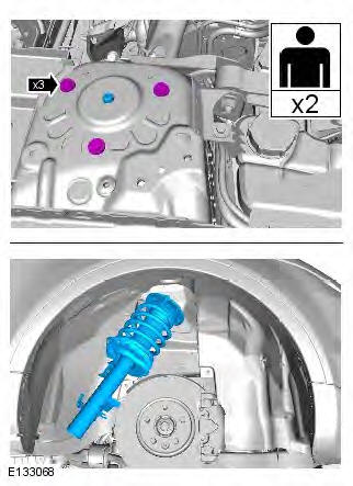
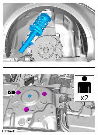
Range Rover Evoque: Shock Absorber and Spring Assembly Vehicles With: Dynamic Suspension
Special Tool(s)
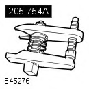 205-754A
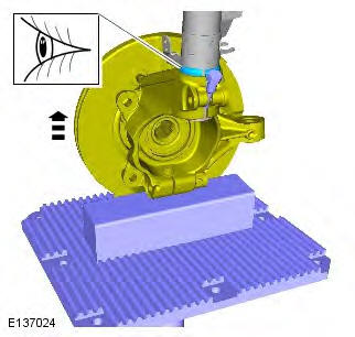
Splitter, Ball Joints
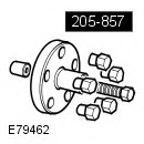 205-857
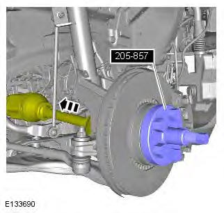
Remover, Halfshaft
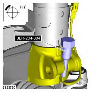
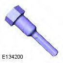 JLR-204-804
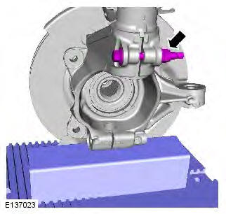
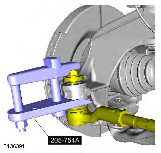
Lever, Wheel Knuckle
General Equipment
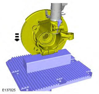
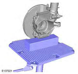
- Transmission jack
- Wooden Block
Removal
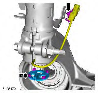
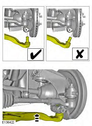
CAUTION: Nuts and bolts must be tightened with the weight of the vehicle on the suspension.
NOTE: Some variation in the illustrations may occur, but the essential information is always correct.
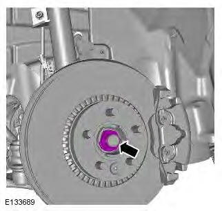
1. WARNING: Make sure to support the vehicle with axle stands. Raise and support the vehicle.
2. Refer to: Wheel and Tire (204-04 Wheels and Tires, Removal and Installation).
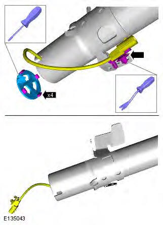
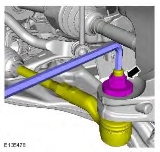
3. CAUTIONS: Do not use air tools to remove the nut.
Discard the nut.
4.

5. CAUTION: Discard the nut.

6. CAUTIONS:
Discard the bolts.
Make sure that no load is placed on the brake hose.
Tie aside with a suitable tie strap.
7.
8.
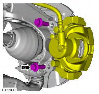
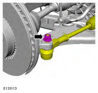
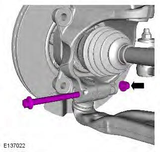
9. CAUTIONS:
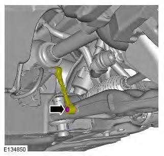
Make sure that the ball joint ball does not rotate.
Discard the nut.
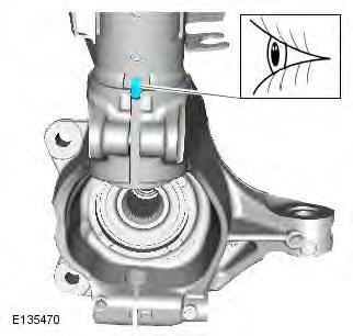
10. CAUTION: Make sure that the ball joint seal is not damaged.
Special Tool(s): 205-754A
11.
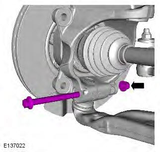
12. CAUTIONS:
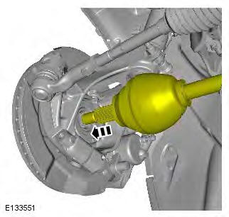
Make sure that the driveshaft is supported with suitable retaining straps.
Do not use a hammer to detach the halfshaft from the hub assembly, failure to follow this instruction may result in damage to the halfshaft.
Special Tool(s): 205-857
13.
- General Equipment: Transmission jack
- General Equipment: Wooden Block

14.

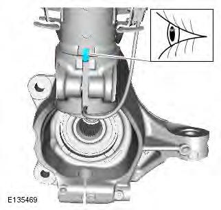
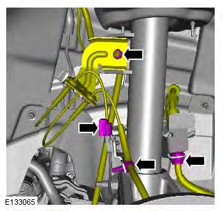
15. CAUTION: Note the fitted position of the component prior to removal.
16. CAUTION: Make sure the wiring harness and electrical connectors are not damaged during this operation.
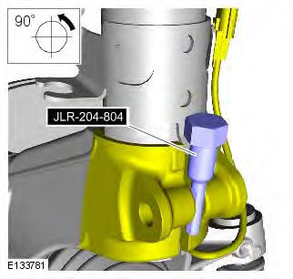
17. Special Tool(s): JLR-204-804
18.
19. NOTE: Note the orientation of the component prior to removal.
Installation
1. NOTE: Make sure that the component is installed to the noted removal position.
Torque: 32 Nm
2.
3. NOTE: Make sure that this component is installed to the noted removal position.
4. Remove the special tool.
5. Torque: 110 Nm
6.
- General Equipment: Transmission jack
- General Equipment: Wooden Block
7. CAUTION: Make sure the wiring harness and electrical connectors are not damaged during this operation.
8.
9. WARNING: Make sure that a new nut is installed.
CAUTION: Make sure that the ball joint ball does not rotate. Torque: 133 Nm
10.
11. Torque: 110 Nm
12. CAUTION: Make sure that new bolts are installed. Torque: 200 Nm

13. WARNING: Make sure that a new nut is installed. Torque: 60 Nm
14.
15. WARNING: Make sure that a new nut is installed.
CAUTIONS: Do not use air tools to install the nut. Failure to follow this instruction may result in damage to the component.
Install the halfshaft nut finger tight.
Tighten the nut without the weight of the vehicle on the suspension.
Torque:
Stage 1: 120 Nm
Stage 2: 60
READ NEXT:
 Rear Suspension AWD
Component Location
RH (right-hand) spring and damper assembly
Stabilizer link
Stabilizer bar
LH (left-hand) spring and damper assembly
Wheel knuckle
Hub
Longitudinal link
Rear transverse lin
Rear Wheel Bearing
Special Tool(s)
204-250
Wheel bearing install and removal tool
204-305
Remover, Wheel Bearing
204-726
Remover/Installer, Wheel Bearing
JLR-204-806
Support Tool, Wheel Knuckle
JLR-204-809
Installer, Re
SEE MORE:
Important information
The information contained in this handbook covers all vehicle derivatives and
optional equipment,
some of which may not be fitted to your vehicle. Due to printing cycles, this
handbook may include
descriptions of options before they become generally available.
The vehicle options, hardware an
Symbols used in this handbook
Safety warnings indicate either a procedure which must be followed
precisely, or
information that should be considered with great care, in order to avoid the
possibility
of personal injury.
Cautions indicate either a procedure which must be followed precisely, or
information that
should
