Range Rover Evoque: Suspension System - General Information
Coil Spring Suspension

Wheel Alignment Specification (All Markets) - Front
NOTE: All figures are with vehicle at 'Showroom' ride height - full fluids, full tank of fuel, no occupants/luggage, tires inflated to normal pressures
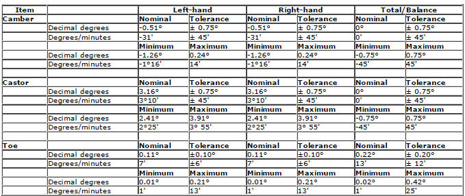
Wheel Alignment Specification (All Markets) - Rear
NOTE: All figures are with vehicle at 'Showroom' ride height - full fluids, full tank of fuel, no occupants/luggage, tires inflated to normal pressures

Vehicle Ride Height
NOTES:
All figures are with vehicle at 'Kerbside' (curbside) ride height - full fluids, full tank of fuel, no occupants/luggage, tires inflated to normal pressures
Ride height is measured vertically from wheel center to underside of wheel arch

Four-Wheel Alignment
1. Check the geometry specifications.
Refer to: Specifications (204-00 Suspension System - General Information, Specifications).
2. Check the tie rod ends, suspension joints, wheel bearings and wheels and tires for damage, wear and free play.
3. Check and adjust tire pressures.
4. Position the vehicle on a calibrated, level, vehicle lift.
5. Release the vehicle parking brake.
6. Using only four wheel alignment equipment approved by Land Rover, check and adjust the wheel alignment.
7. WARNING: Make sure to support the vehicle with axle stands. Raise and support the vehicle.
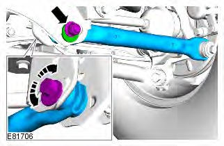
8. Adjust the rear toe.
Torque: 175 Nm
9. Repeat the rear toe measurement.
10. Align the steering to straight ahead.
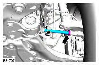
11. Adjust the front toe.
Torque: 100 Nm
12. Check, and if necessary, repeat the wheel alignment procedure until the correct values are obtained.
13. Using the Land Rover approved diagnostic system, calibrate the steering angle sensor.
Suspension System
Principles of Operation
For a detailed description of the Suspension System and operation, refer to the relevant Description and Operation section of the workshop manual.
Inspection and Verification
WARNING: Before carrying out a road test, make sure the vehicle is safe to do so. Failure to follow this instruction may result in personal injury.
CAUTION: Diagnosis by substitution from a donor vehicle is NOT acceptable. Substitution of control modules does not guarantee confirmation of a fault and may also cause additional faults in the vehicle being checked and/or the donor vehicle
NOTE: Check and rectify basic faults before beginning diagnostic routines involving pinpoint tests.
1. Gather as much information from the driver as possible and verify the customer concern by carrying out a road test, as closely as possible reproducing the conditions under which the fault occurs.
2. Visually inspect for obvious signs of mechanical damage.
Visual Inspection
- Tire pressures
- Damaged wheels or tires
- Wheel bearing(s)
- Loose or damaged front or rear suspension components
- Loose, damaged or missing suspension fastener(s)
- Worn or damaged suspension bushing(s)
- Loose, worn or damaged steering system components
- Damaged axle components
- Damaged chassis
3. If an obvious cause for an observed or reported condition is found, correct the cause (if possible) before proceeding to the symptom chart.
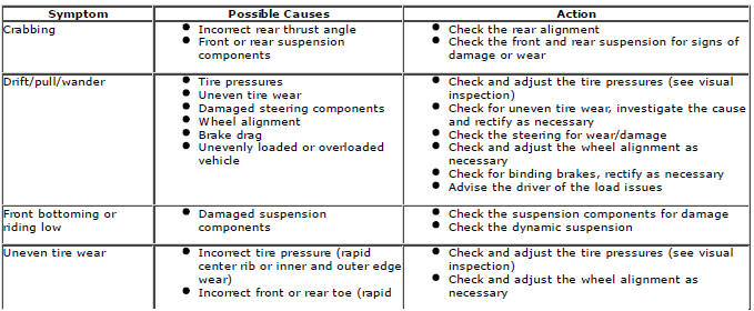
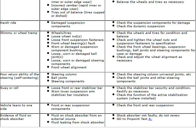
4. If the cause is not visually evident, verify the symptom and refer to the Symptom Chart, alternatively check for Diagnostic Trouble Codes (DTCs) and refer to the DTC Index.
Symptom Chart
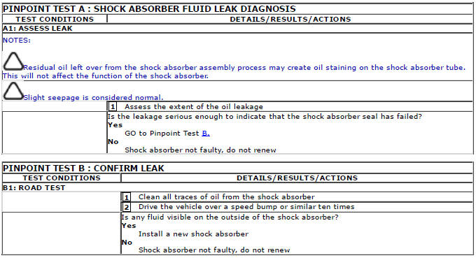
Pinpoint Tests
DTC Index
For a complete list of all diagnostic trouble codes that could be logged on this vehicle, please refer to section 100-00.

