Range Rover Evoque: Front Suspension - Component Location, System Operation and Component Description
Component Location
- RH (right-hand) spring and damper assembly
- Stabilizer bar link
- Stabilizer bar
- LH (left-hand) spring and damper assembly
- Wheel knuckle
- Hub and bearing assembly
- Lower control arm
- Subframe
Overview
The front suspension features long travel McPherson struts to optimize on and off road performance.
The suspension components are mounted on a subframe. The subframe is mounted on four bushes which have differing compression rates to absorb lateral and longitudinal loading. This provides a rigid platform for front suspension cornering loads, frontal impact absorption and also provides a towing point for off-road recovery.
System Operation and Component Description
System Operation
Not applicable.
Component Description
SPRING AND DAMPER
NOTE: Adaptive dynamics damper shown, standard damper similar.
- Locknut
- Bolts - top mount (3 off)
- Upper top mount plate
- Top mount bearing
- Spring isolator
- Spring
- Spring Isolator
- Damper body
- Spring seat
- Damper piston rod
- Spring aid
- Boot
The spring and damper assembly consists of a damper with a coil spring located on a welded spring seat on the damper tube. The lower end of the damper body locates in the wheel knuckle and is clamped with a nut and bolt.
Depending on vehicle specification, the damper is either a conventional damper or a MagneRide damper. The conventional damper functions by restricting the flow of hydraulic fluid through a piston in the damper. The MagneRide damper also functions by restricting the flow of a fluid through the piston, but instead of hydraulic fluid it contains a fluid whose flow properties change when subjected to a magnetic field, which enables the damping rate to be varied.
Refer to: Vehicle Dynamic Suspension (204-05 Vehicle Dynamic Suspension, Description and Operation).
The damper rod is located through a central hole in the top mount assembly. The rod is threaded at its outer end. A self-locking nut secures the damper rod to the top mount. A spring aid is fitted to the top mount bearing to prevent the damper contacting the top mount during full suspension compression, and also to assist the suspension tune. There are different spring aids for conventional and Magneride dampers. The damper rod is sealed at its exit point from the damper body to retain the fluid within the unit and to prevent the ingress of dirt and moisture. The seal also incorporates a wiper to keep the rod clean. A boot is fitted between the damper body and the top mount and protects the damper piston rod from damage.
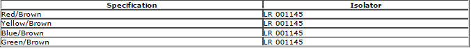
The coil spring fitted differs with vehicle specification. Each spring is color coded to identify its rating and fitment requirements.
The lower end of the coil spring is located in a spring seat which is an integral part of the damper body and contains a spring isolator. The design of the spring seat prevents the spring rotating. The spring has a linear rate compression and is inclined to counter cornering forces. The opposite end of the coil spring is also located in a spring isolator which is fitted in the top mount bearing assembly. Both spring isolators are made from rubber and reduce any noise, produced during damper and spring compression/extension, from being transmitted to the vehicle body.
The top mount bearing is pressed onto the top mount. The top mount bearing reduces steering resistance by preventing the spring from 'winding' up when the steering in turned. The top mount attaches to the suspension turret with three bolts.
Two brackets are welded to the damper body. One bracket provides for the attachment of the stabilizer link. The second bracket provides for the attachment of the brake hose, the wheel speed sensor cable and, on vehicles with dynamic suspension, the MagneRide damper cable. This bracket also positively locates the damper into the wheel knuckle and its location is critical to controlling the vehicle trim height.
LOWER CONTROL ARM
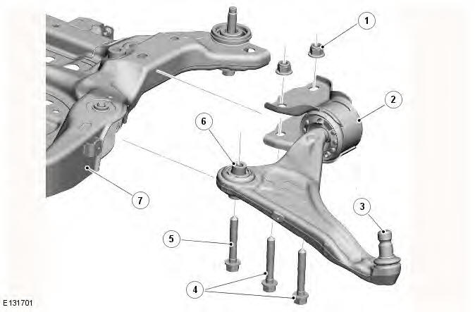
- Nut - rear attachment (2 off)
- Hydrabush
- Taper ball joint
- Bolt - rear attachment (2 off)
- Bolt - front attachment
- Ball bush
- Subframe
The lower control arm assembly consists of a forged aluminum control arm, a rubber bush, a hydrabush and a ball joint.
The ball joint attaches the outer end of the lower control arm to the wheel knuckle. A nut and bolt clamp the ball joint stud to the wheel knuckle.
Two inner attachments locate the inner end of the lower control arm in the subframe. The forward attachment is a non-serviceable rubber bush which is pressed into the control arm. This joint locates in a slot in the subframe and is secured with a bolt which is screwed into a threaded boss on the subframe.
The rearward attachment is a hydrabush which is located on a spigot on the control arm. The hydrabush has two welded brackets which provides for its attachment to the subframe with two bolts and nuts. The hydrabush contains hydraulic fluid and valves which allow controlled displacement of the bush to improve bump and handling characteristics and also reduce road noise transmission. The bush becomes progressively stiffer as the forces on it increase, such as severe braking.
WHEEL KNUCKLE AND HUB
- Clamp bolt
- Locknut
- Wheel knuckle
- ABS (anti-lock brake system) wheel speed sensor mounting
- Steering tie-rod attachment
- Locknut
- Circlip
- Wheel stud
- Wheel hub
- Wheel bearing
- Disc shield attachment
- Clamp bolt
- Brake caliper attachment
The cast steel wheel knuckle provides the attachment for the lower control arm, spring and damper assembly, wheel hub, bearing assembly and the steering tie-rod.
The extended lower boss on the knuckle provides for the attachment of the steering gear tie-rod ball joint.
The upper section of the wheel knuckle has a location hole for the damper body. The damper body slides into the hole and locates against an abutment. The rear face of the hole is split and allows the damper body to be clamped in the wheel knuckle with a nut and bolt.
Mounting locations are provided for the brake caliper and the brake disc shield. A hole in the top face of the wheel knuckle provides the location for the ABS wheel speed sensor, which is secured with a bolt.
The wheel hub is located in the wheel bearing, which is installed in the wheel knuckle and secured with a circlip. The inner face of the wheel bearing incorporates a pulse ring for the ABS sensor.
STABILIZER BAR
- Locknut (hidden)
- Ball joint
- Link
- Ball joint
- Locknut
- Stabilizer bar
- Bush (2 off)
- Nut (4 off)
- Clamp (2 off)
- Collar
- Bolt (4 off)
The stabilizer bar is attached to the rear of the subframe with bushes and mounting brackets. The pressed steel brackets locate over the bushes and are attached to the cross member with nuts and bolts. The stabilizer bar has 'anti-shuffle' collars crimped in position on the inside edges of the bushes. The collars prevent sideways movement of the stabilizer bar.
Each end of the stabilizer bar curves forwards to attach to a ball joint on a stabilizer link. Each stabilizer link is secured to a bracket on the damper body with a locknut. The links, which are not handed, allow the stabilizer bar to move with the wheel travel.
The stabilizer bar bushes are the compression type which grip the bar under compression by the mounting brackets. When fitting replacement bushes, it is important to ensure the bushes have the correct color code and are correctly orientated to the bar. Failure to correctly align the bushes will result in excessive pre-load (wind-up) in the bushes when the suspension is at its nominal ride height.
Front Suspension
Coil Spring Suspension

Road Spring and Isolator Identification
Torque Specifications
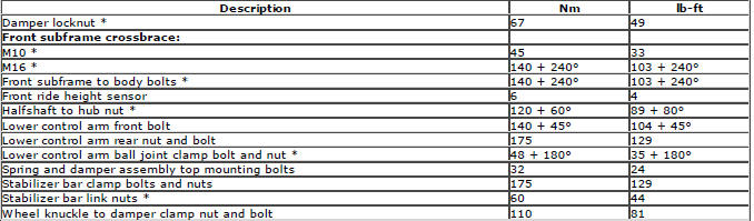
* New nuts/bolts must be installed
READ NEXT:
 Front Wheel Bearing
Special Tool(s)
204-305
Remover, Wheel Bearing
204-726
Remover/Installer, Wheel Bearing
204-727A
Installer, Wheel Bearing
JLR-204-806
Support Tool, Wheel Knuckle
JLR-204-807
Installer, Front Wheel B
Lower Arm
Removal
CAUTION: Nuts and bolts must be tightened with the weight of the vehicle
on the suspension.
NOTES:
RH illustration shown, LH is similar.
Removal steps in this procedure may contain installat
Front Stabilizer Bar AWD
Removal
CAUTION: Nuts and bolts must be tightened with the weight of the vehicle
on the suspension.
NOTES:
Only use clean water as a lubricant for the bushing, if required.
Removal steps in this pro
SEE MORE:
Important information
The information contained in this handbook covers all vehicle derivatives and
optional equipment,
some of which may not be fitted to your vehicle. Due to printing cycles, this
handbook may include
descriptions of options before they become generally available.
The vehicle options, hardware an
Symbols used in this handbook
Safety warnings indicate either a procedure which must be followed
precisely, or
information that should be considered with great care, in order to avoid the
possibility
of personal injury.
Cautions indicate either a procedure which must be followed precisely, or
information that
should
