Range Rover Evoque: Front Wheel Bearing
Special Tool(s)
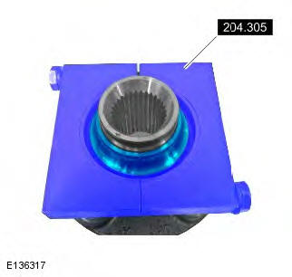
 204-305
Remover, Wheel Bearing
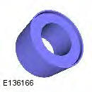
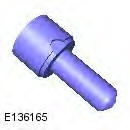
 204-726
Remover/Installer, Wheel Bearing
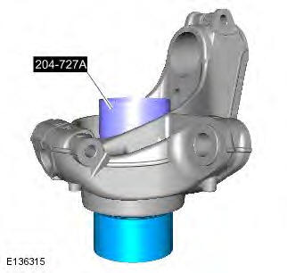
 204-727A
Installer, Wheel Bearing
 JLR-204-806
Support Tool, Wheel Knuckle
 JLR-204-807
Installer, Front Wheel Bearing
 JLR-204-808
Installer, Front Wheel Bearing
General Equipment
- Copper Hammer
- Hydraulic press
- Punch
- Vise
Removal
1. WARNING: Make sure to support the vehicle with axle stands. Raise and support the vehicle.
2. Refer to: Wheel Knuckle (204-01 Front Suspension, Removal and Installation).
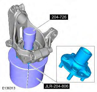
3.
- Special Tool(s): JLR-204-806
- Special Tool(s): 204-726
- General Equipment: Hydraulic press
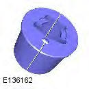
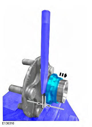
4.
- General Equipment: Vise
- General Equipment: Copper Hammer
- General Equipment: Punch
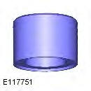
5.
- Special Tool(s): 204-305
- General Equipment: Hydraulic press
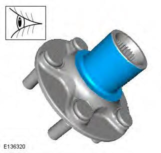
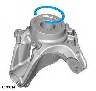
6. Clean all the mating faces and reusable parts thoroughly and check for damage.
7.

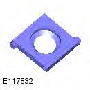
8. NOTE: Note the orientation of the component prior to removal.
- Special Tool(s): 204-727A
- General Equipment: Hydraulic press
Installation
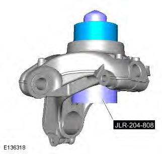
1. CAUTION: Make sure that the area around the component is clean and free of foreign material.
NOTE: Make sure that the component is installed to the noted removal position.
Special Tool(s): JLR-204-808
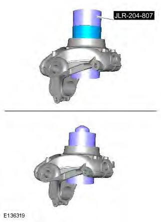
2.
- Special Tool(s): JLR-204-807
- General Equipment: Hydraulic press
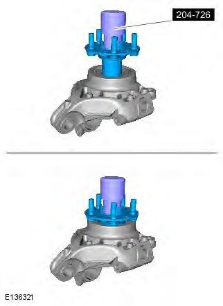
3.
4.
- Special Tool(s): 204-726
- General Equipment: Hydraulic press
5. Refer to: Wheel Knuckle (204-01 Front Suspension, Removal and Installation).
READ NEXT:
 Lower Arm
Removal
CAUTION: Nuts and bolts must be tightened with the weight of the vehicle
on the suspension.
NOTES:
RH illustration shown, LH is similar.
Removal steps in this procedure may contain installat
Front Stabilizer Bar AWD
Removal
CAUTION: Nuts and bolts must be tightened with the weight of the vehicle
on the suspension.
NOTES:
Only use clean water as a lubricant for the bushing, if required.
Removal steps in this pro
Front Stabilizer Bar Bushing
Removal
NOTES:
Some variation in the illustrations may occur, but the essential
information is always correct.
Removal steps in this procedure may contain installation details.
1. WARNING: Make sure
SEE MORE:
Important information
The information contained in this handbook covers all vehicle derivatives and
optional equipment,
some of which may not be fitted to your vehicle. Due to printing cycles, this
handbook may include
descriptions of options before they become generally available.
The vehicle options, hardware an
Symbols used in this handbook
Safety warnings indicate either a procedure which must be followed
precisely, or
information that should be considered with great care, in order to avoid the
possibility
of personal injury.
Cautions indicate either a procedure which must be followed precisely, or
information that
should
