Range Rover Evoque: Wheels and Tires
Wheel and Tire
Removal
NOTE: Removal steps in this procedure may contain installation details.
1. WARNING: Make sure to support the vehicle with axle stands. Raise and support the vehicle.
2. NOTE: Make sure that the component is installed to the position noted on removal.
Installation
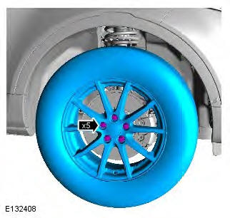
1. CAUTION: Apply a small amount of grease to the hub and wheel mating surfaces before installation. Make sure the grease does not come into contact with the vehicles braking components and the wheel stud threads. Failure to follow these instructions may result in personal injury.
2. NOTE: Tighten the wheel in the sequence shown: Install the wheels and tires.
Torque:
Stage 1: 4 Nm
Stage 2: 70 Nm
Stage 3: 133Nm
Tire Low Pressure Sensor
Removal
CAUTION: If a new sensor is installed, make sure that the sensor frequency is the same as the sensor that has been removed. Failure to follow this instruction may result in the system malfunction.
NOTES:
Removal steps in this procedure may contain installation details.
Some variation in the illustrations may occur, but the essential information is always correct.
1. WARNING: Make sure to support the vehicle with axle stands. Raise and support the vehicle.
2. Refer to: Wheel and Tire (204-04 Wheels and Tires, Removal and Installation).
3. Remove the tire from the wheel, release the tire bead from the rim 180 degrees from the valve.
4.
5.
- Discard the tire valve and retaining nut.
Installation
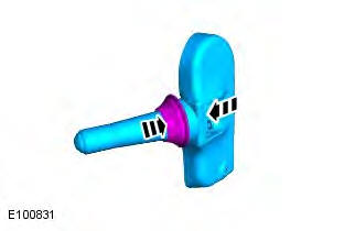
1. CAUTIONS:
Make sure that the seal is correctly located.
Make sure that new components are installed.
Install the washer and seal, making sure the valve remains pressed fully onto its seat.
2. WARNINGS:
Make sure that any corrosion or dirt is removed from the mating surfaces.
Make sure that a new tire valve, valve core, seal, washer, cap and retaining nut is installed.
CAUTIONS:
Use lint free cloth.
Only use moderate force when installing the sensor.
NOTE: Only tighten the nut finger tight at this stage.
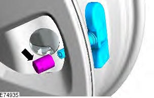
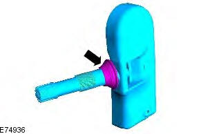
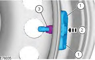
- Install the tire low pressure sensor and support the sensor body in position.
- Support the back of the valve stem in order to prevent rotation to the tire low pressure sensor body.
- Gently push the nut towards the center of the
wheel. Tighten the nut.
Torque: 8 Nm
3. Install the tire and balance the wheel.
4. Refer to: Wheel and Tire (204-04 Wheels and Tires, Removal and Installation).
5. WARNING: Make sure to support the vehicle with axle stands. Lower the vehicle.
Tire Pressure Monitoring System (TPMS) Receiver
Removal
NOTE: Removal steps in this procedure may contain installation details.
All vehicles
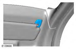
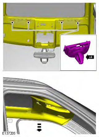
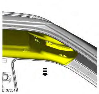
1. NOTE: The procedure must be carried out on both sides. Refer to: A-Pillar Trim Panel (501-05 Interior Trim and Ornamentation, Removal and Installation).
2. Refer to: Overhead Console (501-12 Instrument Panel and Console, Removal and Installation).
All vehicles
3. NOTE: The step must be carried out on both sides.
4. NOTE: The step must be carried out on both sides.
5. NOTE: The step must be carried out on both sides.
6. NOTE: The step must be carried out on both sides.
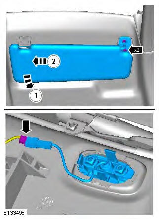
7.
Vehicles with roof opening panel
8. CAUTION: Take extra care not to damage the component.
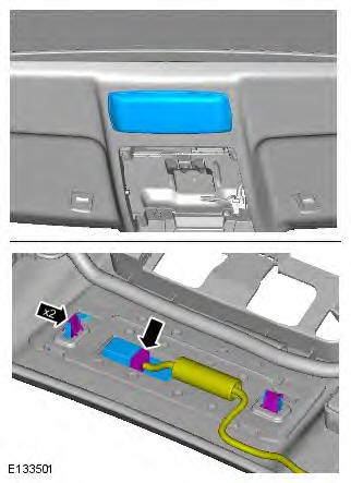
All vehicles
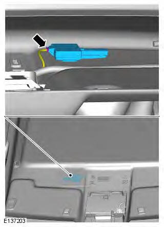
9. CAUTION: Take extra care not to damage the component.
10. CAUTION: Detach the receiver from the headliner by releasing the velcro.
Installation
1. To install, reverse the removal procedure.
2. If a new component has been installed, configure using Land Rover approved diagnostic equipment.
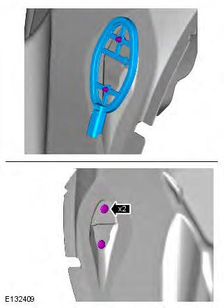
Tire Pressure Monitoring System (TPMS) Front Initiator
Removal
NOTES:
Removal steps in this procedure may contain installation details.
LH illustration shown, RH is similar.
1. WARNING: Make sure to support the vehicle with axle stands. Raise and support the vehicle.
2. Refer to: Wheel and Tire (204-04 Wheels and Tires, Removal and Installation).
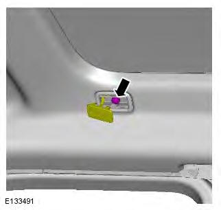
3. CAUTION: Take extra care not to damage the component.
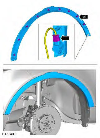
4. Open the front door for access.
5.
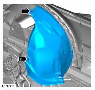
6.
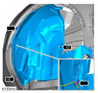
7.

Installation
1. To install, reverse the removal procedure.
2. If a new component has been installed, configure using Land Rover approved diagnostic equipment.
Tire Pressure Monitoring System (TPMS) Rear Initiator
Removal
NOTES:
Removal steps in this procedure may contain installation details.
RH illustration shown, LH is similar.
1. WARNING: Make sure to support the vehicle with axle stands. Raise and support the vehicle.
2. Refer to: Wheel and Tire (204-04 Wheels and Tires, Removal and Installation).
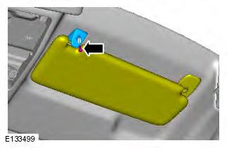
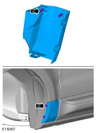
3. CAUTION: Take extra care not to damage the component.
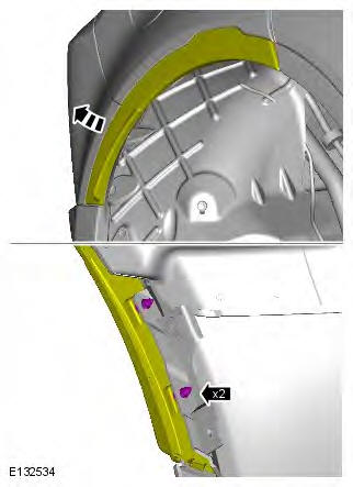
4.
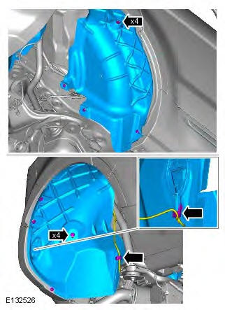
5.
Installation
1. To install, reverse the removal procedure.
2. If a new component has been installed, configure using Land Rover approved diagnostic equipment.
Wheels and Tires - Component Location
NOTE: No full size spare tire is available. Therefore, no tire pressure sensor is built into the spare tire.
Tire Pressure Monitoring System - Component Location
- RH (right-hand) front tire pressure sensor
- CJB (central junction box)
- Tire Pressure Monitoring System (TPMS) Radio Frequency (RF) receiver
- RH rear tire pressure sensor
- RH rear initiator
- Spare tire
- LH (left-hand) rear initiator
- LH rear tire pressure sensor
- Instrument cluster
- LH front tire pressure sensor
- LH front initiator
- BJB (battery junction box)
- Battery
- RH front initiator
Wheels and Tires - Overview
OVERVIEW
Tire Pressure Monitoring System (TPMS)
The purpose of the Tire Pressure Monitoring System (TPMS) is to assist the driver in maintaining the vehicle's tire pressures at the optimum level in order to:
- improve fuel consumption
- maintain ride and handling characteristics
- reduce the risk of rapid tire deflation - which may be caused by under inflated tires
- comply with legislation in relevant markets.
The TPMS measures the pressure in each of the tires on the vehicle and issues warnings to the driver if any of the pressures deviate from defined tolerances.
NOTES:
During a 'blow out' a very rapid reduction in pressure is experienced. The system is not intended to warn the driver of a 'blow out', since it is not possible to give the driver sufficient warning that such an event is occurring, due to its short duration. The design of the TPMS is to assist the driver in keeping the tires at the correct pressure, which will tend to reduce the likelihood of a tire 'blow out' occurring.
TPMS is inhibited when the vehicle is in Delivery mode. For more details on Delivery mode refer to the PDI manual.
A single TPMS hardware configuration is used. TPMS status information is relayed to the driver with a message displayed in the instrument cluster message center and an amber warning indicator.
Tires
WARNING: Care must be taken when removing and refitting tires to ensure that the tire pressure sensor is not damaged.
NOTE: The TPMS valve should be serviced using the suitable service kit, each time the tyre is dismounted, to ensure an air tight seal. Attention should be made to the detail of fitting this kit.
- Tire valve and pressure sensor
- Tire fitting/removal tool initial start position
- High tire and bead tension area
- Low tire and bead tension area
When removing the tire, the bead breaker must not be used within 90 degrees of the tire valve in each direction.
When using the tire removal machine, the fitting arm start position must be positioned as shown in the tire changing illustration. The wheel can then be rotated through 180 degrees in a counterclockwise direction. This will relieve the high tension from the tire bead allowing the remaining 180 degrees of the tire to be manually pulled from the rim.
When refitting the tire, position the fitting arm as shown. Rotate the tire and take care that the bead on the low tension side of the tire does not damage the sensor.
Tread Act - NAS Only
Vehicles supplied to the North American markets must comply with the legislation of the Transport Recall Enhancement, Accountability and Documentation (TREAD) act. Part of the requirement of the TREAD act is for the vehicle to display a label, positioned on the driver's side B-pillar, which defines the recommended tire inflation pressure, load limits and maximum load of passengers and luggage weight the vehicle can safely carry. This label will be specific to each individual vehicle and will be installed on the production line.
This label must not be removed from the vehicle. The label information will only define the specification of the vehicle as it came off the production line. It will not include dealer or owner fitted accessory wheels and tires of differing size from the original fitment.
NOTE: If tires and wheels of a non-standard size are fitted to the vehicle, the car configuration file must be updated using a Land Rover approved diagnostic system.
If the label is damaged or removed for body repair, it must be replaced with a new label specific to that vehicle. A new label is requested from Land Rover parts and will be printed specifically for the supplied VIN of the vehicle.
Wheels and Tires - System Operation and Component Description
Control Diagram
NOTE: A = Hardwired; B = K-Line Bus; F = RF Transmission; D = High Speed CAN (controller area network) Bus; W = LF Transmission

- Battery
- BJB (battery junction box)
- CJB (central junction box)
- RH (right-hand) rear initiator
- LH (left-hand) rear initiator
- RH front initiator
- LH front initiator
- RH rear tire pressure sensor
- LH rear tire pressure sensor
- RH front tire pressure sensor
- LH front tire pressure sensor
- Tire Pressure Monitoring System (TPMS) Radio Frequency (RF) receiver
- Instrument cluster
System Operation
System Operation
Each time the vehicle is driven, the CJB transmits a Low Frequency (LF) (125 KHz) signal to each initiator in turn. This is received by the tire pressure sensor which transmits a Radio Frequency (RF) (315 or 433 MHz depending on market) signal to the RF receiver. This signal contains coded data which corresponds to sensor identification, air pressure, air temperature and acceleration data. This signal is communicated to the CJB via a K-Line Bus.
The system enters 'parking mode' after the vehicle speed has been less than 12.5 mph (20 km/h) for 15 minutes. In parking mode the tire pressure sensors transmit a coded signal to the CJB once every 13 hours. If the tire pressure decreases by more than 1 lbf/in2 (0.6 bar), the sensor will transmit more often if pressure is being lost.
As each wheel responds to the LF signal from the CJB, it is assigned a position on the vehicle and is monitored for the remainder of that drive cycle in that position.
When the vehicle has been parked for more than 15 minutes and then driven at a speed of more than 12.5 mph (20 km/h), the initiators fire in turn for 18 seconds in the following order:
- Front left
- 6 second pause (for the system to detect a response from the tire pressure sensor)
- Front right
- 6 second pause
- Rear right
- 6 second pause
- Rear left
- 6 second pause.
Each tire pressure sensor responds in turn so the CJB can establish the sensor positions at the start of the drive cycle.
This process is repeated up to three times but less if the sensor positions are already known in the CJB. The process is known as 'Auto Location' and takes up to 8 minutes to complete. During this period the tire sensors transmit at regular intervals, once every 15 seconds. For the remainder of the drive cycle the tire sensors transmit once every 60 seconds or if a change in tire pressure is sensed until the vehicle stops and the system returns to parking mode.
Once the wheel position is established, the initiators stop firing a signal and do not fire again until the vehicle has been parked for more than 15 minutes. The signal transmissions from each wheel sensor continue at 1 minute intervals whilst the vehicle is being driven. This transmission is to monitor the tire pressure.
At 25% deflation the amber warning indicator in the instrument cluster is illuminated and an appropriate message displayed in the message center.
Component Description
Tire Location
Because of the requirement for different pressure targets and thresholds for the front and rear tires, the CJB can identify the location of the tires on the vehicle, and assign a received tire pressure sensor identification to a specific position on the vehicle (i.e. FL (front left), FR (front right), RL (rear left) or RR (rear right) ).
Tire location is performed automatically by the CJB using an auto-location function. This function requires no manual intervention by the driver. The CJB can automatically learn the position of tires on the vehicle if the tire pressure sensors or their positions are changed on the vehicle.
The tire learn and location process is ready to commence when the vehicle has been stationary or is traveling at less than 12 mph (20 km/h) for 15 minutes. This is known as 'parking mode'. The learn/locate process requires the vehicle to be driven at speeds of more than 12 mph (20 km/h) for 15 minutes. If the vehicle speed reduces to below 12 mph (20 km/h), the learn process timer is suspended until the vehicle speed increases to more than 12 mph (20 km/h), after which time the timer is resumed. If the vehicle speed remains below 12 mph (20 km/h) for more than 15 minutes, the timer is set to zero and process starts again.
The CJB can automatically detect, under all operating conditions, the following:
- one or more tire pressure sensors have been replaced
- one or more tire pressure sensor identifications are missing
- one or more 'alien' identifications are being received, i.e. the CJB can reject identifications from tire pressure sensors that do not belong to the vehicle
- the spare tire and one of the tires in use on the vehicle have exchanged position on the vehicle.
If the tire pressure sensors fitted to the running wheels (not the spare) are changed, the CJB can learn the new sensor identifications automatically. The learn function requires no manual intervention by the driver.
Spare Tire Identification
Depending on the vehicle specification, the spare tire may or may not be fitted with a tire pressure sensor.
NOTE: Tire pressure sensors cannot be fitted to steel space saver spare wheels.
If the spare tire is being monitored and the driver replaces a flat 'running' tire with the spare tire, the CJB will not continually warn the driver that the original flat tire (now in the spare position) is flat. This prevents distraction of the driver by constant pressure warnings being issued. The driver is reminded by a message displayed for 20 seconds at each ignition on cycle that the spare tire is flat.
Radio Frequency (RF) Receiver
The RF receiver is mounted on headliner next to overhead console and connects to the vehicle harness via a fly lead.
The RF receiver receives transmissions from each of the tire pressure sensors via an internal antenna. This information is then communicated to the CJB via a dedicated LIN (local interconnect network) bus.
Initiator
The initiators are located at the front of the front wheel arches and at the rear of the rear wheel arches and are secured with two scrivets. The TPMS has four initiators and each has a connector which connects with the body harness.
The initiator is a passive, Low Frequency (LF) transmitter. Each initiator provides an auto-location feature to identify tire positions on the vehicle and transmit that data to the CJB.
The CJB energizes each initiator in turn using LF drivers. The corresponding tire pressure sensor detects the resulting LF transmission and responds by initiating an RF transmission of its data. This data is received by the RF receiver and communicated to the CJB via a K-Line Bus. The CJB can then determine which sensor is transmitting and its location on the vehicle.
Tire Pressure Sensor
The TPMS system uses 'active' tire pressure sensors which are mounted on each wheel, inside the tire cavity. The sensor is retained in position by the valve attachment to the wheel structure. The sensors transmit their RF signals at either 315 MHz or 433 MHz dependent on market requirements.
The sensors periodically measure the pressure and temperature of the air inside the tire plus the centripetal acceleration acting on the sensor. These measurements are transmitted periodically to the RF receiver located behind the overhead console.
The tire pressure sensors are self-contained units which have no electrical connections into or out of the sensor.
The care points detailed in the 'Tires' section of this chapter must be followed to avoid damage to the sensor. If the sensor is replaced, the nut, seal and washer must also be replaced and the sensor tightened to the correct torque value as given in the Service Repair manual.
The RF transmission from the sensor contains a unique identification code in its transmission data, so that the CJB can identify the tire on the vehicle. If the sensor is replaced on a 'running' wheel, the new sensor identification will be learnt when the vehicle is first driven at a speed of more than 12.5 mph (20 km/h) for 15 minutes. If a new sensor is fitted to the spare wheel, the identification for that sensor must be programmed into the CJB using a Land Rover approved diagnostic system or that wheel will not be monitored. The code is provided on a label with the complete wheel and tire assembly when new and is also printed on the casing of each sensor.
In order to conserve battery power, the tire sensor module uses different transmission rates when the wheel is stationary or moving. The wheel speed required to change between the stationary and moving transmission rates is very low to allow for the requirement for slow off-road driving.
Instrument Cluster Indications
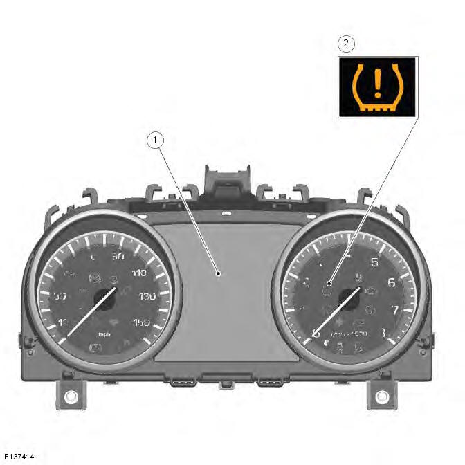
- Message center
- Amber warning indicator
The warning indications to the driver are common on all vehicles fitted with TPMS. Warnings are conveyed by an amber LED (light emitting diode) warning indicator and a text message displayed in the message center.
The warning indicator and message center are driven by CAN messages from the CJB. The warning indicator is illuminated by the cluster software for 3 seconds when the vehicle is in power mode 6 for a bulb check.
For additional information, refer to: (413-08 Information and Message Center)
Controller Area Network (CAN)
The CJB sends and receives a number of digital messages via CAN. The received messages are used for the operation of the TPMS. The transmitted messages comprise of TPMS status and requests to the instrument cluster to illuminate warnings indicators and/or display messages in the message center.
Transmitted Messages
The CJB transmits the messages shown in the following table.

Diagnostics
The CJB has a diagnostic connection via the high speed CAN to enable system status and faults to be retrieved using a Land Rover approved diagnostic system.
Additionally, an on-board diagnostic routine within the CJB constantly monitors the system and alerts the driver to system faults by illuminating the amber warning indicator and/or displaying a message in the instrument cluster message center.
Fault Detection
If a sensor fails, the amber warning indicator in the instrument cluster will be illuminated. A message 'XX Tyre Not Monitored' will be displayed in the message center in addition to the amber warning indicator.
NOTE: 'XX' is the tire position on the vehicle, e.g. FL (front left), FR (front right), RL (rear left) or RR (rear right).
If more than one sensor fails or the CJB develops a fault, the amber warning indicator will be illuminated. A message 'Tyre Monitoring System Fault' will be displayed in the message center in addition to the amber warning indicator. This fault could also be caused if RF interference near the vehicle affects the system signal reception. When the interference has ceased, the fault will be automatically cancelled and the TPMS will operate normally.
If a tire pressure sensor battery voltage becomes low, the sensor transmits a message to the CJB. The CJB stores the low battery condition as a fault flag in its memory with no other visual warnings displayed. If the battery fails, the sensor will stop transmitting and the CJB will transmit a message to display 'FL Tyre Not Monitored' for example in the message center. The dealer should interrogate the CJB for the fault flag using a Land Rover approved diagnostic system to determine the cause of the message. If the battery has failed, the sensor must be replaced and the stored fault flags removed using a Land Rover approved diagnostic system. The CJB will learn the identification of the new sensor when the vehicle is driven. If the replaced sensor is fitted to the spare wheel (if fitted), its identification must be manually programmed into the CJB using a Land Rover approved diagnostic system or by using it as a 'running' wheel for 15 minutes at more than 12.5 mph (20 km/h), then replacing it to the spare wheel position.
Wheels and Tires
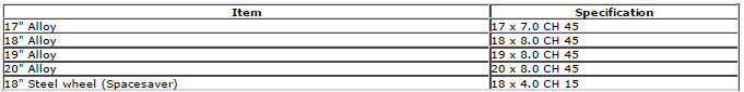
Wheel Type
CAUTION: CAUTION: With reduced size spare wheel fitted, do not exceed 50 mph (80 km/h) and replace with standard size wheel at earliest opportunity.
Tire Sizes - Standard Fit
CAUTION: CAUTION: Inner tubes must not be fitted with any of these tires.
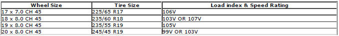
Tire Sizes - Accessory Fit
CAUTION: CAUTION: Inner tubes must not be fitted with any of these tires.

Tire Pressures
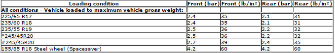
* 0 - 160 KPH (0 - 100 MPH).
# 160 KPH (100 MPH).
Recommended Lubricant

Torque Specifications

* Road wheel nuts must be tightened by diagonal selection
Tire Pressure Monitoring System (TPMS)
Principles of Operation
For a detailed description of the wheels and tires, refer to the relevant Description and Operation section in the workshop manual.
Inspection and Verification
CAUTION: Diagnosis by substitution from a donor vehicle is NOT acceptable. Substitution of control modules does not guarantee confirmation of a fault, and may also cause additional faults in the vehicle being tested and/or the donor vehicle.
1. Verify the customer complaint. As much information as possible should be gathered from the driver to assist in diagnosing the cause(s). Confirm which of the following two warning types (A or B) exist for the Tire Pressure Monitoring System when the ignition status is switched from 'OFF' to 'ON'
- (A) Check Tire Pressure Warnings. A low tire pressure warning will
continuously illuminate the low tire
pressure warning lamp. This warning may be accompanied by a text message
such as CHECK TIRE PRESSURE
(refer to owner literature). The manufacturer approved diagnostic system
does NOT need to be used.
Diagnostic Trouble Codes (DTCs) are not generated with this type of warning. To extinguish this warning it is essential that, with the ignition 'ON', all vehicle tires (including the spare) are to be set to the correct pressure as stated in the vehicle handbook or as indicated on the placard label in the passenger/driver door aperture. It is not necessary to drive the vehicle to clear 'check tire pressure' warnings - just changing the tire pressure causes the tire low pressure sensor to transmit new data.
NOTES:
The tire pressures should be set by:
- Using a calibrated tire pressure gauge
- With 'cold' tires (vehicle parked in the ambient temperature for at least one hour, not in a garage with an artificial ambient temperature)
If the tire pressure warning does not clear within two minutes, it is likely that the gauge is not correctly calibrated or the tires are 'warm'. Carry out the following steps until the warning has cleared:
- Increase the tire pressures by 3psi
- Wait a further two minutes
- When the tires are at ambient temperature and a calibrated gauge is available, reset the tire pressures to the correct pressure.
Tire pressure adjustments are part of routine owner maintenance. Tire pressure adjustments that are required due to a lack of owner maintenance are not to be claimed under vehicle warranty.
- (B) System Fault Warnings. When a system fault is detected, the low tire pressure warning lamp will flash for approximately 75 seconds prior to being continuously illuminated. Visually inspect for obvious signs of damage and system integrity. Check for the presence of tire low pressure sensors on all four wheels (note: a tire low pressure sensor has a metal valve stem rather than a rubber one).
2. Check for Diagnostic Trouble Codes (DTCs) and refer to the relevant DTC Index.
Inspection and Verification
1. Verify the customer concern.
2. Visually inspect for obvious signs of mechanical or electrical damage.
Visual Inspection
- Tire pressures
- Damaged wheels or tires
3. If an obvious cause for an observed or reported concern is found, correct the cause (if possible) before proceeding to the next step.
4. If the cause is not visually evident, verify the symptom and refer to the Symptom Chart.
DTC Index
For a complete list of all diagnostic trouble codes that could be logged on this vehicle, please refer to section 100-00.
READ NEXT:
 Vehicle Dynamic Suspension
Vehicle Dynamic Suspension - Component
Location
COMPONENT LOCATION
RH (right-hand) rear spring and damper assembly
RH rear height sensor
LH (left-hand) rear spring and damper assembly
LH rear he
Ride and Handling Optimization
Ride and Handling Optimization AWD
COMPONENT LOCATION
Terrain Response switchpack and control module
OVERVIEW
The Terrain Response system allows the driver to select a program which aims
to prov
SEE MORE:
Important information
The information contained in this handbook covers all vehicle derivatives and
optional equipment,
some of which may not be fitted to your vehicle. Due to printing cycles, this
handbook may include
descriptions of options before they become generally available.
The vehicle options, hardware an
Symbols used in this handbook
Safety warnings indicate either a procedure which must be followed
precisely, or
information that should be considered with great care, in order to avoid the
possibility
of personal injury.
Cautions indicate either a procedure which must be followed precisely, or
information that
should
